Features
∑ Well-defined spatial radiation
pattern
∑ Viewing angles:
Major axis 120∞
Minor axis 60∞
∑ High luminous output
∑ AlInGaP II (brightest) intensity
level
∑ Colors:
472 nm blue
526 nm green
630 nm red
592 nm amber
∑ Superior resistance to moisture
∑ UV resistant epoxy
Benefits
∑ Viewing angle designed for wide
field of view applicaion
∑ Superior performance in outdoor
environments
Applications
∑ Full color signs
CAUTION: The Blue and Green LEDs are Class 1 ESD sensitive. Please observe appropriate precautions
during handling and processing. Refer to Agilent Application Note AN-1142 for additional details.
Agilent HLMP-SL11, HLMP-RL11,
HLMP-SD11, HLMP-RD11, HLMP-RB11,
HLMP-RM11 4 mm Oval Precision
Optical Performance Best Value
AlInGaP and InGaN Lamps
Data Sheet
High efficiency LED materials are
used in these lamps: Higher
performance of Aluminum Indium
Gallium Phosphide (AlInGaP II)
for Red and Amber color and
Indium Gallium Nitride (InGaN)
for Blue and Green. Each lamp is
made with an advanced optical
grade epoxy offering superior
high temperature and high
moisture resistance in outdoor
applications. The package epoxy
contains both UV-A and UV-B
inhibitors to reduce the effects of
long term exposure to direct
sunlight.
Designers can select parallel or
perpendicular orientation. Both
lamps are available in tinted
version.
Description
These Precision Optical
Performance Oval LEDs are
specifically designed for Full Color/
Video and Passenger Information
signs. The Oval shaped radiation
pattern (60∞ x 120∞) and high
luminous intensity ensure that these
devices are excellent for wide field
of view outdoor applications where
a wide viewing angle and readability
in sunlight are essential. These
lamps have very smooth, matched
radiation patterns ensuring
consistent color mixing in full color
applications, message uniformity
across the viewing angle of the sign.
2
Selection Guide for AlInGaP II
Color and
Luminous
Dominant
Intensity,
Wavelength
d
I
v
(mcd)
Leads with
Leadframe
Package
Part Number
(nm) Typ.
Min.
Stand-Offs
Orientation
Drawing
HLMP-SL11-H0000
Amber 592
180
Yes
Perpendicular
A
HLMP-RL11-H0000
Amber 592
180
Yes
Parallel
B
HLMP-SD11-J0000
Red 630
240
Yes
Perpendicular
A
HLMP-RD11-J0000
Red 630
240
Yes
Parallel
B
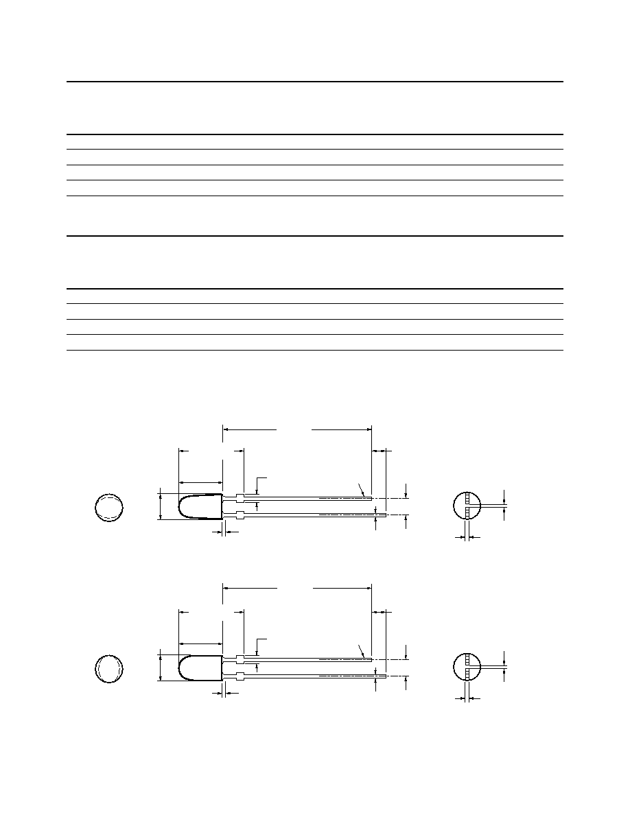
Package Dimensions
Selection Guide for InGaN
Color and
Luminous
Dominant
Intensity,
Wavelength
d
I
v
(mcd)
Leads with
Leadframe
Package
Part Number
(nm) Typ.
Min.
Stand-Offs
Orientation
Drawing
HLMP-RB11-D0000
Blue 472
65
Yes
Parallel
B
HLMP-RB11-H0000
Blue 472
180
Yes
Parallel
B
HLMP-RM11-H0000
Green 526
180
Yes
Parallel
B
HLMP-RM11-M0000
Green 526
520
Yes
Parallel
B
4.0 ± 0.20
(0.157 ± 0.008)
1.25 ± 0.20
(0.049 ± 0.008)
0.80
(0.016)
MAX. EPOXY MENISCUS
9.50 ± 0.50
(0.374 ± 0.020)
CATHODE
LEAD
A
6.30 ± 0.20
(0.248 ± 0.008)
2.54 ± 0.30
(0.100 ± 0.012)
21.00
(0.827)
MIN.
1.00
(0.039)
MIN.
0.40
+0.10
≠0
(0.016
+0.004
≠0.000)
0.45
+0.10
≠0.04
(0.018
+0.004
≠0.002)
4.0 ± 0.20
(0.157 ± 0.008)
1.25 ± 0.20
(0.049 ± 0.008)
0.80
(0.016)
MAX. EPOXY MENISCUS
9.50 ± 0.50
(0.374 ± 0.020)
CATHODE
LEAD
B
6.30 ± 0.20
(0.248 ± 0.008)
2.54 ± 0.30
(0.100 ± 0.012)
21.00
(0.827)
MIN.
1.00
(0.039)
MIN.
0.40
+0.10
≠0
(0.016
+0.004
≠0.000)
0.45
+0.10
≠0.04
(0.018
+0.004
≠0.002)
DIMENSIONS ARE IN MILLIMETERS (INCHES).
0.44 ± 0.20
(0.017 ± 0.008)
0.44 ± 0.20
(0.017 ± 0.008)

3
Absolute Maximum Ratings at T
A
= 25∞C
Parameter
Blue and Green
Red and Amber
DC Forward Current
[1]
30 mA
50 mA
Peak Pulsed Forward Current
100 mA
100 mA
Average Forward Current
30 mA
30 mA
Reverse Voltage (I
R
= 100
µA)
5 V
5 V
Power Dissipation
120 mW
120 mW
LED Junction Temperature
100∞C
110∞C
Operating Temperature Range
≠40∞C to +80∞C
≠40∞C to +100∞C
Storage Temperature Range
≠40∞C to +100∞C
≠40∞C to +120∞C
Wave Soldering Temperature
250∞C for 3 sec.
250∞C for 3 sec.
Note:
1. Derate linearly as shown in Figure 6 and 7.
Electrical/Optical Characteristics at T
A
= 25∞C
Parameter
Symbol
Min.
Typ.
Max.
Units
Test Conditions
Typical Viewing Angle
Major
2
1/2
120
deg
Minor
60
Forward Voltage
V
F
I
F
= 20 mA
Amber (
d
= 592 nm)
2.15
2.5
V
Red (
d
= 630 nm)
2.00
2.5
Blue (
d
= 472 nm)
3.5
4.0
Green (
d
= 526 nm)
3.5
4.0
Reverse Voltage
Amber, Red
V
R
5
20
V
I
R
= 100
µA
Blue, Green
5
--
I
R
= 10
µA
Peak Wavelength
Peak of Wavelength
Amber (
d
= 592 nm)
peak
594
nm
of Spectral Distribution
Red (
d
= 630 nm)
639
at I
F
= 20 mA
Blue (
d
= 472 nm)
470
Green (
d
= 526 nm)
524
Spectral Halfwidth
Wavelength Width
Amber (
d
= 592 nm)
1/2
17
nm
at Spectral Distribution
Red (
d
= 630 nm)
17
1/2 Power Point at
Blue (
d
= 472 nm)
35
I
F
= 20 mA
Green (
d
= 526 nm)
47
Capacitance
V
F
= 0, F = 1 MHz
Amber, Red
C
40
pF
Blue, Green
43
Luminous Efficacy
Emitted Luminous
Amber (
d
= 592 nm)
v
500
lm/W
Power/Emitted Radiant
Red (
d
= 630 nm)
155
Power at I
F
= 20 mA
Blue (
d
= 472 nm)
75
Green (
d
= 526 nm)
520
Thermal Resistance
R
J-PIN
240
∞C/W
LED Junction-to-Cathode
Lead
Notes:
1. 2
1/2
is the off-axis angle where the luminous intensity is 1/2 the on-axis intensity.
2. The radiant intensity, I
e
in watts per steradian, may be found from the equation I
e
= I
v
/
v
where I
v
is the luminous intensity in candelas and
v
is
the luminous efficacy in lumens/watt.
3. The luminous intensity is measured on the mechanical axis of the lamp package.
4. The optical axis is closely aligned with the package mechanical axis.
5. The dominant wavelength
d
is derived from the CIE Chromaticity Diagram and represents the color of the lamp.
4
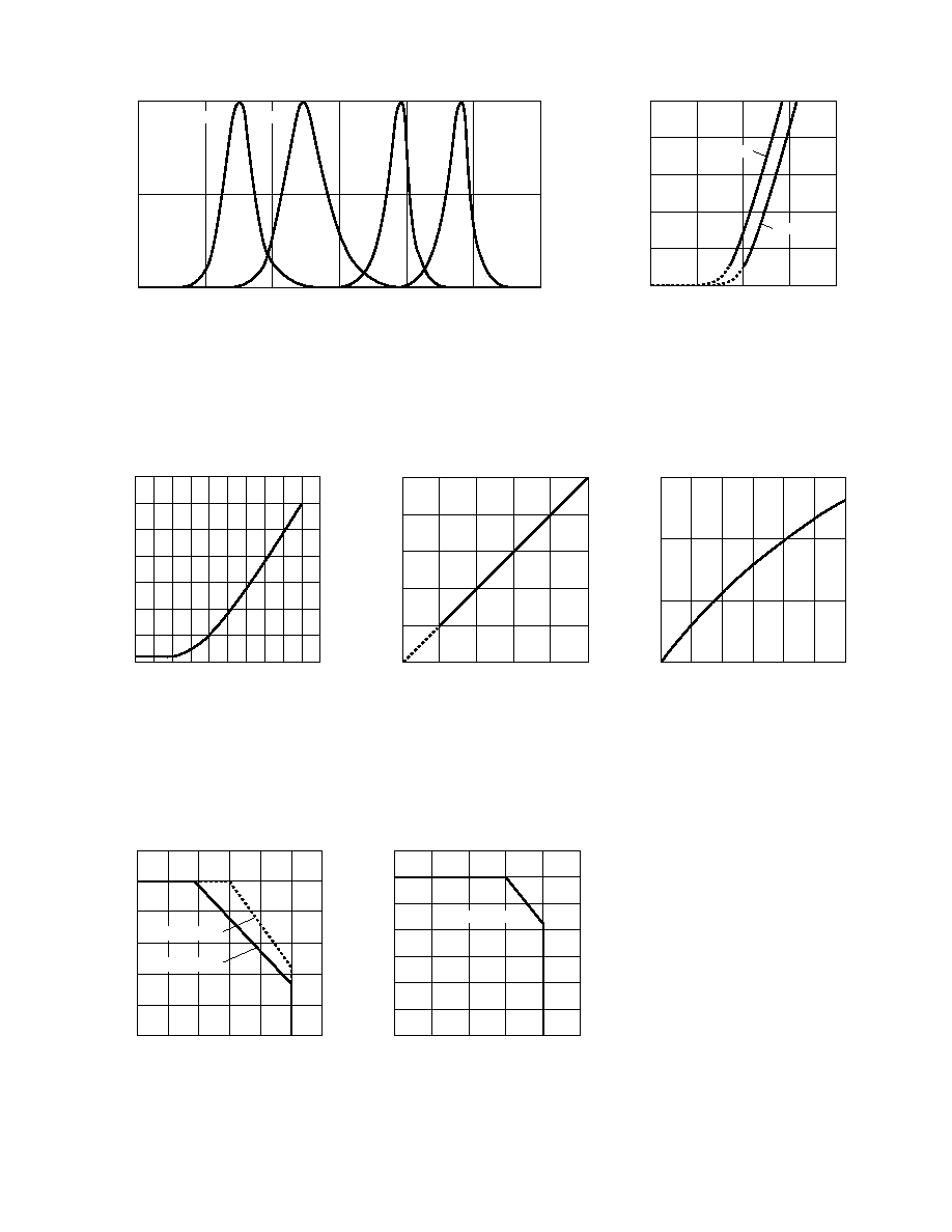
Figure 1. Relative intensity vs. wavelength.
Figure 2. Amber, red forward current vs.
forward voltage.
Figure 3. Blue, green forward current vs.
forward voltage.
Figure 4. Amber, red relative luminous
intensity vs. forward current.
Figure 5. Blue, green relative luminous
intensity vs. forward current.
Figure 6. Amber, red maximum forward
current vs. ambient temperature.
Figure 7. Blue, green maximum forward
current vs. ambient temperature.
WAVELENGTH ≠ nm
RELATIVE INTENSITY
1.0
0.5
0
600
700
400
650
550
500
450
BLUE
GREEN
AMBER
RED
0
40
20
I F
≠
FORWARD CURRENT
≠
mA
VF ≠ FORWARD VOLTAGE ≠ V
3.0
1.5
2.0
2.5
10
30
50
1.0
RED
AMBER
0
30
15
I F
≠
FORWARD CURRENT
≠
mA
VF ≠ FORWARD VOLTAGE ≠ V
4.0
2.4
2.8
3.2
10
20
35
2.0
3.6
5
25
RELATIVE LUMINOUS INTENSITY
(NORMALIZED AT 20 mA)
0
0
IF ≠ FORWARD CURRENT ≠ mA
20
40
2.0
1.0
50
0.5
1.5
2.5
30
10
RELATIVE LUMINOUS INTENSITY
(NORMALIZED AT 20 mA)
0
IF ≠ FORWARD CURRENT ≠ mA
15
25
1.0
30
0.5
1.5
20
5
10
0
I F
≠
FORWARD CURRENT
≠
mA
0
0
TA ≠ AMBIENT TEMPERATURE ≠ ∞C
40
80
50
40
30
20
10
20
60
100
60
120
R
J-A = 780∞C/W
R
J-A = 585∞C/W
I F
≠
FORWARD CURRENT
≠
mA
0
0
TA ≠ AMBIENT TEMPERATURE ≠ ∞C
40
80
30
25
20
15
5
20
60
100
35
R
J-A = 585∞C/W
10
5
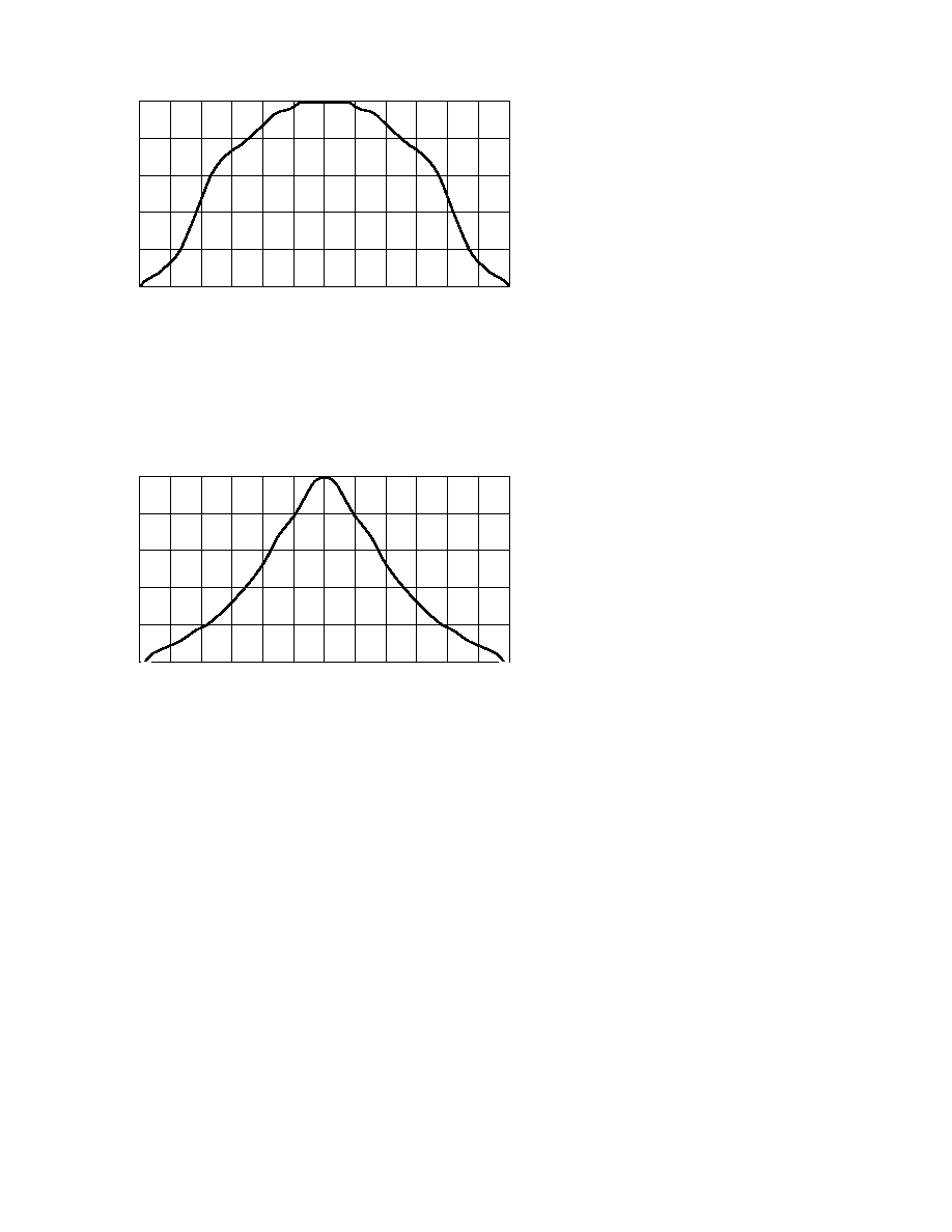
Figure 8a. Representative spatial radiation pattern for major axis.
Figure 8b. Representative spatial radiation pattern for minor axis.
RELATIVE INTENSITY
1.0
0
ANGULAR DISPLACEMENT ≠ DEGREES
0.8
0.6
0.2
-90
0.4
-60
-30
15
45
90
-15
30
-75
75
-45
60
0
RELATIVE INTENSITY
1.0
0
ANGULAR DISPLACEMENT ≠ DEGREES
0.8
0.6
0.2
-90
0.4
-60
-30
15
45
90
-15
30
-75
75
-45
60
0