Features
∑ Rectangular Light Emitting
Surface
∑ Excellent for Flush
Mounting on Panels
∑ Choice of Five Bright Colors
∑ Long Life: Solid State
Reliability
∑ Excellent Uniformity of
Light Output
Description
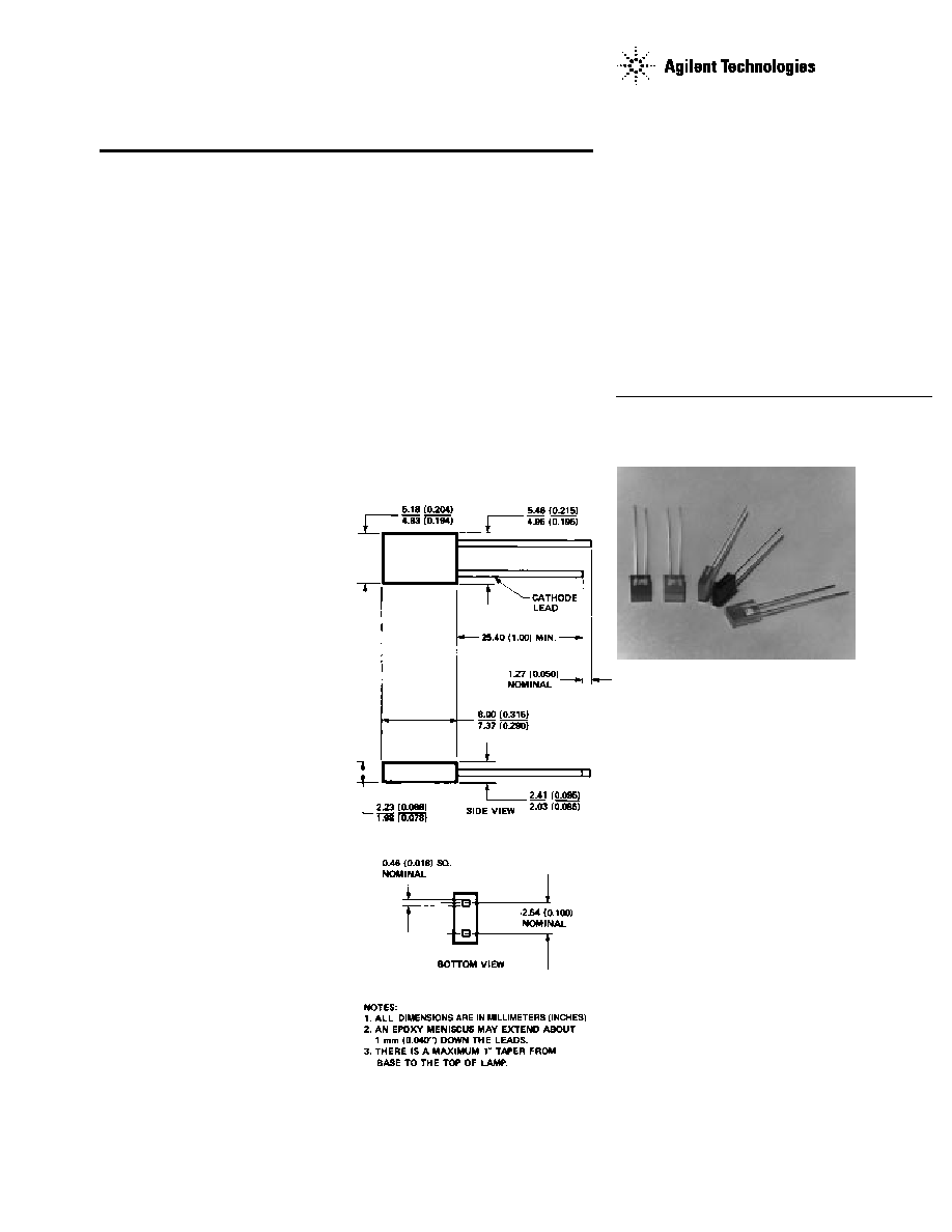
The HLMP-S100, -S201, -5301,
-S400, -S401, -S501, -S600 are
epoxy encapsulated lamps in
rectangular packages which are
easily stacked in arrays or used
for discrete front panel indicators.
Contrast and light uniformity are
enhanced by a special epoxy
diffusion and tinting process.
The HLMP-S100 uses double
heterojunction (DH) absorbing
substrate (AS) aluminum gallium
arsenide (AlGaAs) LEDs to
produce outstanding light output
over a wide range of drive
currents.
2 mm x 5 mm Rectangular
LED Lamps
Technical Data
HLMP-S100
HLMP-S201
HLMP-S301
HLMP-S400
HLMP-S401
HLMP-S501
HLMP-S600
Package Dimensions
2
Selection Guide
Luminous Intensity Iv (mcd) at 20 mA
Color
Part Number
Min.
Typ.
Max.
AlGaAs Red
HLMP-S100
3.4
7.5
≠
HER
HLMP-S201
HLMP-S201-D00xx
2.1
3.5
≠
HLMP-S201-E00xx
3.4
7.5
≠
HLMP-S201-EF0xx
3.4
7.5
10.8
Orange
HLMP-S400
2.1
3.5
≠
HLMP-S401
3.4
7.5
≠
Yellow
HLMP-S301
HLMP-S301-B00xx
1.4
2.1
≠
HLMP-S301-C00xx
2.2
4.0
≠
HLMP-S301-CDBxx
2.2
4.0
7.2
Green
HLMP-S501
HLMP-S501-C00xx
2.6
4.0
≠
HLMP-S501-D00xx
4.2
8.0
≠
HLMP-S501-DE0xx
4.2
8.0
13.4
Emerald Green
[1]
HLMP-S600-A00xx
1.0
3.0
≠
Note:
1. Please refer to Application Note 1061 for information comparing standard green and emerald green light output degradation.
Part Numbering System
HLMP - S x xx - x x x xx
Mechanical Option
00: Bulk
02: Tape & Reel, Straight Leads
DG: Ammo Pack
Color Bin Options
0: Full Color Bin Distribution
B: Color Bins 2 & 3 only
Maximum Iv Bin Options
0: Open (no max. limit)
Others: Please refer to the Iv Bin Table
Minimum Iv Bin Options
Please refer to the Iv Bin Table
Brightness Level
00: Less Brightness
01: Higher Brightness
Color Options
1: AlGaAs Red
2: GaP HER
3: GaP Yellow
4: GaP Orange
5: GaP Green
6: GaP Emerald Green
3
Sym.
Description
Device HLMP-
Min.
Typ.
Max.
Units
Test Conditions
2
1/2
Included Angle
All
110
Deg.
I
F
= 20 mA
Between Half
See Note 1
Luminous
Intensity Points
PEAK
Peak Wavelength
AlGaAs Red
645
nm
Measurement at
High Efficiency Red
635
Peak
Orange
600
Yellow
583
Green
565
Emerald Green
558
d
Dominant
AlGaAs Red
637
nm
See Note 2
Wavelength
High Efficiency Red
626
Time const, e
-t/
s
Orange
602
Yellow
585
Green
569
Emerald Green
560
s
Speed of
AlGaAs Red
30
ns
Response
High Efficiency Red
90
Orange
280
Yellow
90
Green
500
Emerald Green
3100
C
Capacitance
AlGaAs Red
30
pF
V
F
= 0; f = 1 MHz
High Efficiency Red
11
Orange
4
Yellow
15
Green
18
Emerald Green
35
R
J-PIN
Thermal
All
260
∞
C/W
Junction to Cathode
Resistance
Lead at Seating
Plane
V
F
Forward Voltage
AlGaAs Red
1.6
1.8
2.2
V
I
F
= 20 mA
HER/Orange
1.5
1.9
2.6
Yellow
1.5
2.1
2.6
Green/Emerald
1.5
2.2
3.0
Green
V
R
Reverse Break-
All
5.0
V
I
R
= 100
µ
A
down Voltage
V
Luminous
AlGaAs Red
80
Efficacy
High Efficiency Red
145
Orange
380
lumens/
See Note 3
Yellow
500
watt
Green
595
Emerald Green
656
Electrical/Optical Characteristics at T
A
= 25
∞
C
Notes:
1.
1/2
is the off-axis angle at which the luminous intensity is half the axial luminous intensity.
2. The dominant wavelength,
d
, is derived from the CIE chromaticity diagram and represents the single wavelength which defines the
color of the device.
3. Radiant intensity, I
e
, in watts/steradian, may be found from the equation I
e
= I
v
/
v
, where I
v
is the luminous intensity in candelas and
v
is the luminous efficacy in lumens/watt.
4. Please refer to Application Note 1061 for information comparing standard green and emerald green light output degradation.
4
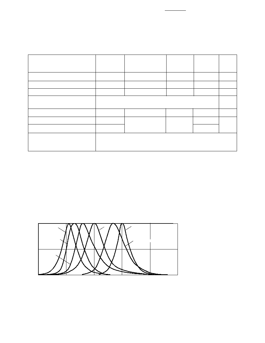
Figure 1. Relative Intensity vs. Wavelength.
Green/
AlGaAs
High Efficiency
Emerald
Parameter
Red
Red/Orange
Yellow
Green
Units
Peak Forward Current
300
90
60
90
mA
Average Forward Current
[1]
20
25
20
25
mA
DC Current
[2]
30
30
20
30
mA
Transient Forward Current
[3]
500
mA
(10
µ
sec Pulse)
LED Junction Temperature
110
110
110
110
∞
C
Operating Temperature Range
-20 to +100
-20 to +100
-55 to +100
-55 to +100
∞
C
Storage Temperature Range
-55 to +100
-55 to +100
Lead Soldering Temperature
[1.6 mm (0.063 in.) below
260
∞
C for 5 seconds
seating plane]
Notes:
1. See Figure 5 to establish pulsed operating conditions.
2. For AlGaAs Red, Red, Orange, and Green series derate linearly from 50
∞
C at 0.5 mA/
∞
C. For Yellow series derate linearly from 50
∞
C at
0.34 mA/
∞
C.
3. The transient peak current is the maximum non-recurring peak current that can be applied to the device without damaging the LED
die and wire bond. It is not recommended that the device be operated at peak currents beyond the peak forward current listed in the
Absolute Maximum Ratings.
Absolute Maximum Ratings at T
A
= 25
∞
C
ORANGE
AlGaAs RED
HIGH EFFICIENCY RED
WAVELENGTH ≠ nm
RELATIVE INTENSITY
1.0
0.5
0
500
550
600
650
700
YELLOW
EMERALD GREEN
HIGH
PERFORMANCE
GREEN
T = 25∞ C
A
5
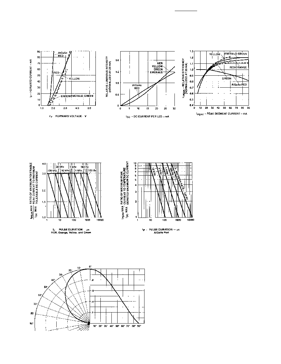
Figure 4. Relative Efficiency
(Luminous Intensity per Unit Current)
vs. LED Peak Current.
v (300 mA) for
AlGaAs Red = 0.7.
Figure 2. Forward Current vs.
Forward Voltage Characteristics. V
F
(300 mA) for AlGaAs Red = 2.6 Volts
Typical.
Figure 3. Relative Luminous Intensity
vs. DC Forward Current.
Figure 5. Maximum Tolerable Peak Current vs. Peak Duration.
(I
PEAK
MAX Determined from Temperature Derated I
DC
MAX).
Figure 6. Relative Luminous Intensity vs. Angular Displacement.