4 mm Oval Precision Optical
Performance LED Lamps
Data Sheet
Features
∑ Well defined spatial radiation
pattern
∑ Viewing angle:
major axis 120
∞
minor axis 60
∞
∑ High luminous output
∑ Two red and amber intensity
levels
AlInGaP (bright) and
AlInGaP II (brightest)
∑ Colors
626/630 nm red
590/592 nm amber
526 nm green
470 nm blue
∑ Superior resistance to moisture
∑ UV resistant epoxy
Benefits
∑ Viewing angle designed for wide
field of view applications
∑ Superior performance for outdoor
environments
∑ Radiation pattern matched for red,
green, and blue for full color sign
Applications
∑ Full color signs
Description
These Precision Optical Perfor-
mance Oval LEDs are specifically
designed for Full Color/Video and
Passenger Information signs. The
oval shaped radiation pattern
(60
∞
x 120
∞
) and high luminous
intensity ensure that these de-
vices are excellent for wide field
of view outdoor applications
where a wide viewing angle and
readability in sunlight are essen-
tial. These lamps have very
smooth, matched radiation pat-
terns ensuring consistent color
mixing in full color applications,
message uniformity across the
viewing angle of the sign.
High efficiency LED materials are
used in these lamps: Aluminum
Indium Gallium Phosphide
(AlInGaP) for Red and Amber
color and Indium Gallium Nitride
(InGaN) for Blue and Green.
There are two families of red and
amber lamps, AlInGaP and the
higher performance AlInGaP II.
Each lamp is made with an
advanced optical grade epoxy
offering superior high tempera-
ture and high moisture resistance
in outdoor applications. The
package epoxy contains both uv-a
and uv-b inhibitors to reduce the
effects of long term exposure to
direct sunlight.
Designers can select parallel
(where the axis of the leads is
parallel to the wide axis of the
oval radiation pattern) or perpen-
dicular orientation. Both lamps
are available in tinted version.
SunPower Series
Agilent HLMP-RG10, HLMP-SG10, HLMP-RL10, HLMP-SL10,
HLMP-RD11, HLMP-SD11, HLMP-RL11, HLMP-SL11,
HLMP-RM11, HLMP-SM11, HLMP-RB11, HLMP-SB11
CAUTION: The Blue and Green LEDs are Class 1 ESD sensitive. Please observe appropriate precautions during
handling and processing. Refer to Agilent Technologies Application Note AN-1142 for additional details.
2
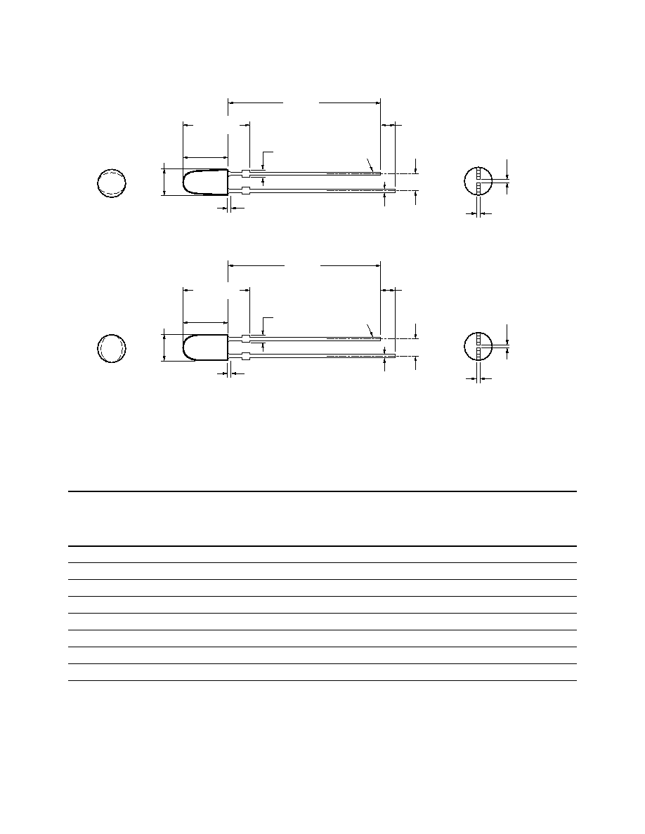
Package Dimensions
4.0 ± 0.20
(0.157 ± 0.008)
1.25 ± 0.20
(0.049 ± 0.008)
0.80
(0.016)
MAX. EPOXY MENISCUS
9.50 ± 0.50
(0.374 ± 0.007)
0.44 ± 0.20
(0.017 ± 0.008)
CATHODE
LEAD
A
6.30 ± 0.20
(0.248 ± 0.008)
2.54 ± 0.30
(0.100 ± 0.012)
21.0
(0.827)
MIN.
1.0
(0.039)
MIN.
0.40
+0.10
≠0
(0.016
+0.004
≠0.000)
0.45
+0.10
≠0.04
(0.018
+0.004
≠0.002)
4.0 ± 0.20
(0.157 ± 0.008)
1.25 ± 0.20
(0.049 ± 0.008)
0.80
(0.016)
MAX. EPOXY MENISCUS
9.50 ± 0.50
(0.374 ± 0.007)
0.44 ± 0.20
(0.017 ± 0.008)
CATHODE
LEAD
B
6.30 ± 0.20
(0.248 ± 0.008)
2.54 ± 0.30
(0.100 ± 0.012)
21.0
(0.827)
MIN.
1.0
(0.039)
MIN.
0.40
+0.10
≠0
(0.016
+0.004
≠0.000)
0.45
+0.10
≠0.04
(0.018
+0.004
≠0.002)
DIMENSIONS ARE IN MILLIMETERS (INCHES).
Notes:
1. The luminous intensity is measured on the mechanical axis of the lamp package.
2. The optical axis is closely aligned with the package mechanical axis.
3. The dominant wavelength,
d
, is derived from the CIE Chromaticity Diagram and represents the color of the lamp.
Device Selection Guide for AlInGaP
Color and
Luminous
Dominant
Intensity
Wavelength
I
V
(mcd) at 20 mA
Leads with
Leadframe
Package
Part Number
d
(nm) Typ.
Min. Max.
Stand-Offs
Orientation
Drawing
HLMP-SG10-GK000
Red 626
120 460
Yes
Perpendicular
A
HLMP-RG10-GK000
Red 626
120 460
Yes
Parallel
B
HLMP-SG10-JM000
Red 626
205 780
Yes
Perpendicular
A
HLMP-RG10-JM000
Red 626
205 780
Yes
Parallel
B
HLMP-SL10-FJ000
Amber 590
96 360
Yes
Perpendicular
A
HLMP-RL10-FJ000
Amber 590
96 360
Yes
Parallel
B
HLMP-SL10-HL000
Amber 590
155 600
Yes
Perpendicular
A
HLMP-RL10-HL000
Amber 590
155 600
Yes
Parallel
B

3
Notes:
1. The luminous intensity is measured on the mechanical axis of the lamp package.
2. The optical axis is closely aligned with the package mechanical axis.
3. The dominant wavelength,
d
, is derived from the CIE Chromaticity Diagram and represents the color of the lamp.
Device Selection Guide for AlInGaP II
Color and
Luminous
Dominant
Intensity
Wavelength
I
V
(mcd) at 20 mA
Leads with
Leadframe
Package
Part Number
d
(nm) Typ.
Min. Max.
Stand-Offs
Orientation
Drawing
HLMP-SD11-LP000
Red 630
345 1330
Yes
Perpendicular
A
HLMP-RD11-LP000
Red 630
345 1330
Yes
Parallel
B
HLMP-SD11-LPT00
Red 630
345 1330
Yes
Perpendicular
A
HLMP-RD11-LPT00
Red 630
345 1330
Yes
Parallel
B
HLMP-SD11-MNT00
Red 630
450 1010
Yes
Perpendicular
A
HLMP-SL11-HLR00
Amber 592
155 600
Yes
Perpendicular
A
HLMP-SL11-LP000
Amber 592
345 1330
Yes
Perpendicular
A
HLMP-RL11-LP000
Amber 592
345 1330
Yes
Parallel
B
HLMP-SL11-LPR00
Amber 592
345 1330
Yes
Perpendicular
A
HLMP-RL11-LPR00
Amber 592
345 1330
Yes
Parallel
B
HLMP-SL11-LPV00
Amber 592
345 1330
Yes
Perpendicular
A
HLMP-RL11-LPV00
Amber 592
345 1330
Yes
Parallel
B
Device Selection Guide for InGaN
Color and
Luminous
Dominant
Intensity
Wavelength
I
V
(mcd) at 20 mA
Leads with
Leadframe
Package
Part Number
d
(nm) Typ.
Min. Max.
Stand-Offs
Orientation
Drawing
HLMP-SM11-LP000
Green 526
345 1330
Yes
Perpendicular
A
HLMP-RM11-LP000
Green 526
345 1330
Yes
Parallel
B
HLMP-SB11-EH000
Blue 470
70 270
Yes
Perpendicular
A
HLMP-RB11-LP000
Blue 470
70 270
Yes
Parallel
B
Notes:
4. The luminous intensity is measured on the mechanical axis of the lamp package.
5. The optical axis is closely aligned with the package mechanical axis.
6. The dominant wavelength,
d
, is derived from the CIE Chromaticity Diagram and represents the color of the lamp.
4
Absolute Maximum Ratings
T
A
= 25
∞
C
Parameter
Blue and Green
Amber and Red
DC Forward Current
[1]
30 mA
50 mA
Peak Pulsed Forward Current
100 mA
100 mA
Average Forward Current
30 mA
30 mA
Reverse Voltage (I
R
= 100
µ
A)
5 V
5 V
Power Dissipation
120 mW
120 mW
LED Junction Temperature
100
∞
C
130
∞
C
Operating Temperature Range
≠40
∞
C to +80
∞
C
≠40
∞
C to +100
∞
C
Storage Temperature Range
≠40
∞
C to +100
∞
C
≠40
∞
C to +120
∞
C
Soldering Temperature
260
∞
for 5 sec
260
∞
for 5 sec
Note:
1. Derate linearly as shown in Figures 6 and 7.
Note:
1. For Amber color, '0` includes color bins 1, 2, 4, and 6 only.
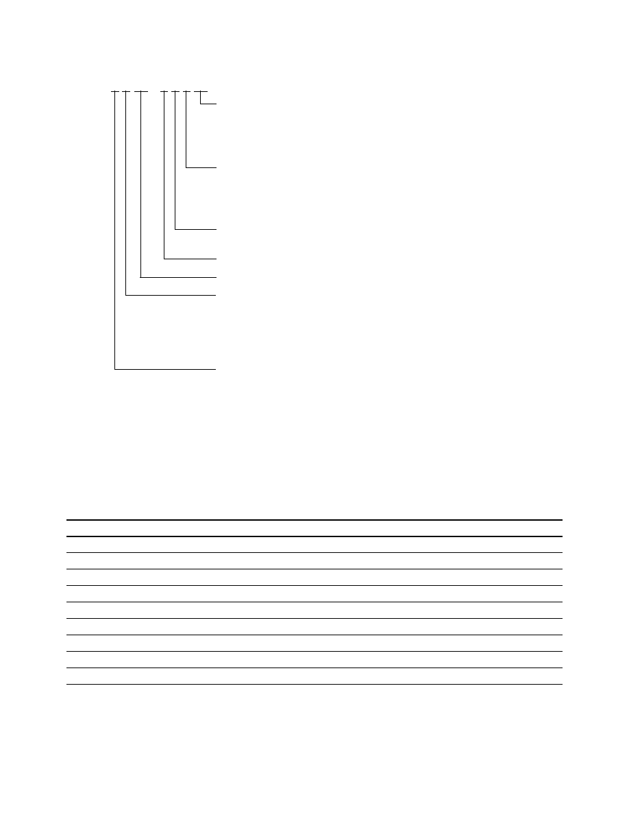
Part Numbering System
HLMP - x x xx - x x x xx
Mechanical Options
00: Bulk Packaging
DD: Ammo Pack
YY: Flexi-Bin; Bulk Packaging
ZZ: Flexi-Bin; Ammo Pack
Color Bin & V
F
Selections
0: No Color Bin Limitation
[1]
R: Amber Color Bins 1, 2, 4, 6, and 7 with V
F
Maximum of 2.6 V
T: Red Color with V
F
Maximum of 2.6 V
V: Amber Color Bins 1, 2, 4, and 6 with V
F
Maximum of 2.6 V
Maximum Intensity Bin
0: No Iv Bin Limitation
Minimum Intensity Bin
Refer to Device Selection Guide
Color
B: 470 nm Blue
D: 630 nm Red
G: 626 nm Red
L: 590/592 nm Amber
M: 526 nm Green
Package
R: 4 mm 60∫ x 120∫ Oval, Parallel
S: 4 mm 60∫ x 120∫ Oval, Perpendicular

5
Electrical/Optical Characteristics
T
A
= 25
∞
C
Parameter
Symbol
Min.
Typ.
Max.
Units
Test Conditions
Typical Viewing Angle
[1]
2
1/2
deg
Major
120
Minor
60
Forward Voltage
V
F
V
I
F
= 20 mA
Red (
d
= 626 nm)
1.9
2.4
Red (
d
= 630 nm)
2.0
2.4
[2]
Amber (
d
= 590 nm)
2.02
2.4
Amber (
d
= 592 nm)
2.15
2.4
[2]
Blue (
d
= 470 nm)
3.5
4.0
Green (
d
= 526 nm)
3.5
4.0
Reverse Voltage
V
R
V
I
R
= 100
µ
A
Amber and Red
5
20
Blue and Green
5
≠
Peak Wavelength
PEAK
nm
Peak of Wavelength of
Red (
d
= 626 nm)
635
Spectral Distribution
Red (
d
= 630 nm)
639
at I
F
= 20 mA
Amber (
d
= 590 nm)
592
Amber (
d
= 592 nm)
594
Notes:
1. 2
1/2
is the off-axis angle where the luminous intensity is the on-axis intensity.
2. For options -xxRxx, -xxTxx, and -xxVxx, maximum forward voltage, V
F
, is 2.6 V.
3. The radiant intensity, I
e
, in watts per steradian, may be found from the equation I
e
= I
v
/
v
, where I
v
is the luminous intensity in candelas and
v
is
the luminous efficacy in lumens/watt.
LED Indicators
Parameter
Symbol
Min.
Typ.
Max.
Units
Test Conditions
Blue (
d
= 470 nm)
467
Green (
d
= 526 nm)
524
Spectral Halfwidth
1/2
nm
Wavelength Width at
Red (
d
= 626/630 nm)
17
Spectral Distribution
Amber (
d
= 590/592 nm)
17
1
/
2
Power Point at I
F
= 20 mA
Blue (
d
= 470 nm)
20
Green (
d
= 526 nm)
35
Capacitance
C
pF
V
F
= 0, F = 1 MHz
All Colors
40
Thermal Resistance
R
J-PIN
∞
C/W
LED Junction-to-Cathode
All Colors
240
Lead
Luminous Efficacy
[3]
v
lm/W
Emitted Luminous Power/
Red (
d
= 626 nm)
150
Emitted Radiant Power
Red (
d
= 630 nm)
155
Amber (
d
= 590 nm)
480
Amber (
d
= 592 nm)
500
Blue (
d
= 470 nm)
70
Green (
d
= 526 nm)
540