Subminiature High Performance
AlInGaP LED Lamps
Technical Data
Features
∑ Subminiature Flat Top
Package
Ideal for Backlighting and Light
Piping Applications
∑ Subminiature Dome Package
Nondiffused Dome for High
Brightness
∑ Wide Range of Drive
Currents
∑ Colors: 590 nm Amber,
605 nm Orange, 615 nm
Reddish-Orange, 626 nm
Red, and 635 nm Red
∑ Ideal for Space Limited
Applications
∑ Axial Leads
∑ Available with Lead
Configurations for Surface
Mount and Through Hole PC
Board Mounting
Description
Flat Top Package
The HLMX-PXXX flat top lamps
use an untinted, nondiffused,
truncated lens to provide a wide
radiation pattern that is neces-
sary for use in backlighting
applications. The flat top lamps
are also ideal for use as emitters
in light pipe applications.
Dome Packages
The HLMX-QXXX dome lamps
use an untinted, nondiffused lens
to provide a high luminous
intensity within a narrow
radiation pattern.
Lead Configurations
All of these devices are made by
encapsulating LED chips on axial
lead frames to form molded
epoxy subminiature lamp
packages. A variety of package
configuration options is available.
These include special surface
mount lead configurations, gull
wing, yoke lead, or Z-bend. Right
angle lead bends at 2.54 mm
(0.100 inch) and 5.08 mm (0.200
inch) center spacing are available
for through hole mounting. For
more information refer to
Standard SMT and Through Hole
Lead Bend Options for
Subminiature LED Lamps data
sheet.
Technology
These subminiature solid state
lamps utilize one of the two newly
developed aluminum indium
gallium phosphide (AlInGaP)
LED technologies, either the
absorbing substrate carrier
technology (AS = HLMA-
Devices) or the transparent
substrate carrier technology
(TS = HLMT-Devices). The TS
HLMT-Devices are especially
effective in very bright ambient
lighting conditions. The colors
590 nm amber, 605 nm orange,
615 nm reddish-orange, 626 nm
red, and 635 nm red are available
with viewing angles of 15
∞
for the
domed devices and 125
∞
for the
flat top devices.
SunPower Series
HLMA-PF00
HLMT-PG00
HLMA-PG00
HLMT-PH00
HLMA-PH00
HLMT-PL00
HLMA-PL00
HLMT-QG00
HLMA-QF00
HLMT-QH00
HLMA-QG00 HLMT-QL00
HLMA-QH00
HLMA-QL00
2
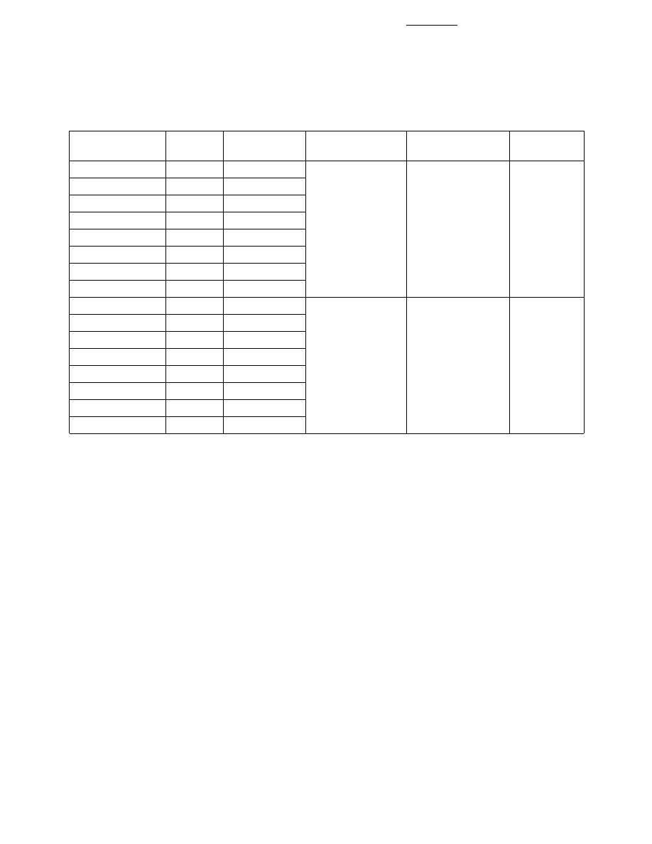
Device Selection Guide
Package
Viewing
Package
Part Number
d
(nm)
Typ. Iv (mcd)
Description
Angle 2
1
/
2
Outline
HLMA-QL00
590
500
Domed,
15
∞
B
HLMT-QL00
590
1000
Nondiffused,
HLMA-QJ00
605
500
Untinted
HLMA-QH00
615
500
HLMT-QH00
615
800
HLMA-QG00
626
500
HLMT-QG00
626
1000
HLMA-QF00
635
500
HLMA-PL00
590
75
Flat Top,
125
∞
A
HLMT-PL00
590
150
Nondiffused,
HLMA-PJ00
605
75
Untinted
HLMA-PH00
615
75
HLMT-PH00
615
120
HLMA-PG00
626
75
HLMT-PG00
626
150
HLMA-PF00
635
75
3
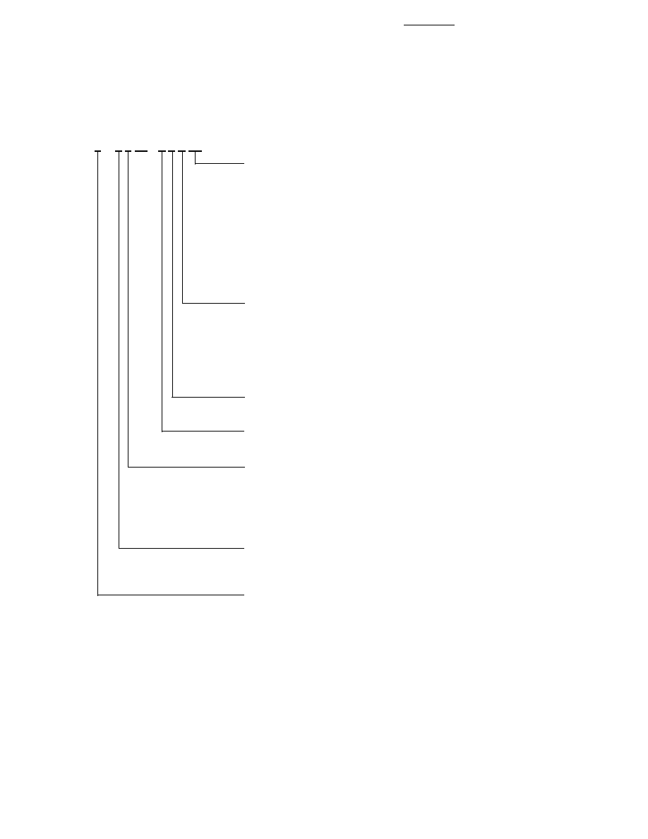
Part Numbering System
HLMx - x x 00 - x x x xx
Packaging Option
00: Straight Leads, Bulk Packaging, Quantity of 500 parts
11: Gull Wing Bend, Tape & Reel ≠ 7" Reel
12: Gull Wing Bend, Bulk
14: Gull Wing Bend, Tape & Reel ≠ 13" Reel
21: Yoke Bend, Tape and Reel ≠ 7" Reel
22: Yoke Bend, Bulk
24: Yoke Bend, Tape and Reel ≠ 13" Reel
31: Z-Bend, Tape and Reel ≠ 7" Reel
32: Z-Bend, Bulk
34: Z-Bend, Tape and Reel ≠ 13" Reel
Color Bin Selection
0:
Full Color Bin Distribution
B: Color Bins 3 & 4
K: Color Bins 2, 3 & 4
R: Color Bins 2 & 4
W: Color Bins 2, 4, 6 & 7
X: Color Bins 4, 6 & 7
Maximum Iv Bin Options
Please refer to the Iv Bin Table
Minimum Iv Bin Options
Please refer to the Iv Bin Table
Color Options
L:
Amber 590 nm
J:
Orange 605 nm
H: Reddish Orange 615 nm
G: Red 626 nm
F: Red 635 nm
Package Options
Q: Dome
P: Flat Top
Dice Options
A: AS AlInGaP
T: TS AlInGaP
4
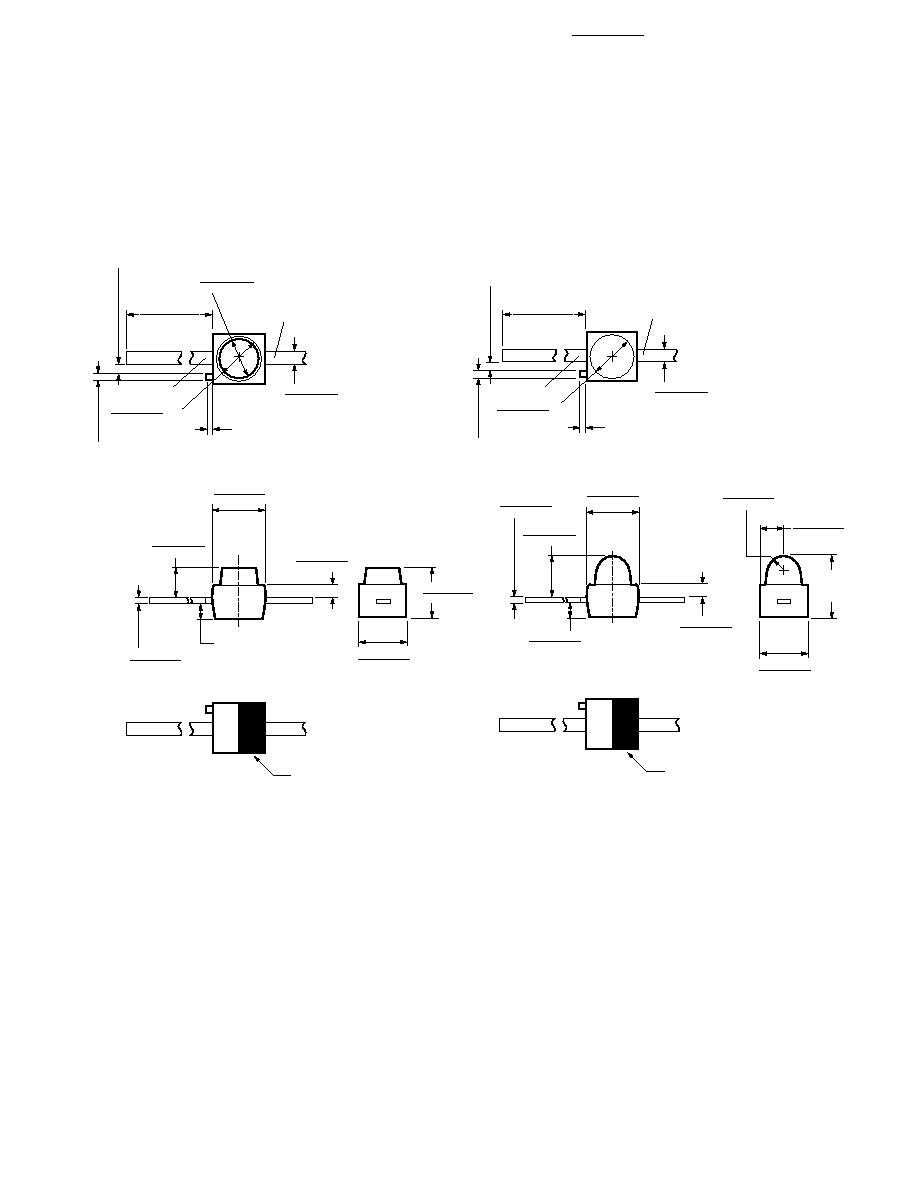
Package Dimensions
(A) Flat Top Lamps
(B) Domed Lamps, Diffused and Nondiffused
1.14
1.40
(0.045)
(0.055)
0.63
0.38
(0.025)
(0.015)
2.21
1.96
(0.087)
(0.077)
0.18
0.23
(0.007)
(0.009)
2.44
1.88
(0.096)
(0.074)
2.08
2.34
(0.082)
(0.092)
CATHODE
STRIPE
0.46
0.56
(0.018)
(0.022)
1.40
1.65
(0.055)
(0.065)
0.25 (0.010) MAX.
NOTE 2
0.20 (0.008) MAX.
0.50 (0.020) REF.
CATHODE
1.65
1.91
(0.065)
(0.075)
DIA.
ANODE
11.68
10.67
(0.460)
(0.420)
BOTH SIDES
0.79 (0.031) MAX.
0.94
1.24
(0.037)
(0.049)
2.92
(0.115)
MAX.
0.76
0.89
(0.030)
(0.035)
R.
0.63
0.38
(0.025)
(0.015)
2.03 (0.080)
1.78 (0.070)
0.79 (0.031)
0.53 (0.021)
0.18
0.23
(0.007)
(0.009)
2.08
2.34
(0.082)
(0.092)
NOTES:
1. ALL DIMENSIONS ARE IN MILLIMETRES (INCHES).
2. PROTRUDING SUPPORT TAB IS CONNECTED TO CATHODE LEAD.
0.50 (0.020) REF.
0.46
0.56
(0.018)
(0.022)
0.25 (0.010) MAX.
NOTE 2
0.20 (0.008) MAX.
CATHODE
1.65
1.91
(0.065)
(0.075)
DIA.
ANODE
11.68
10.67
(0.460)
(0.420)
BOTH SIDES
2.21
1.96
(0.087)
(0.077)
CATHODE
STRIPE
5
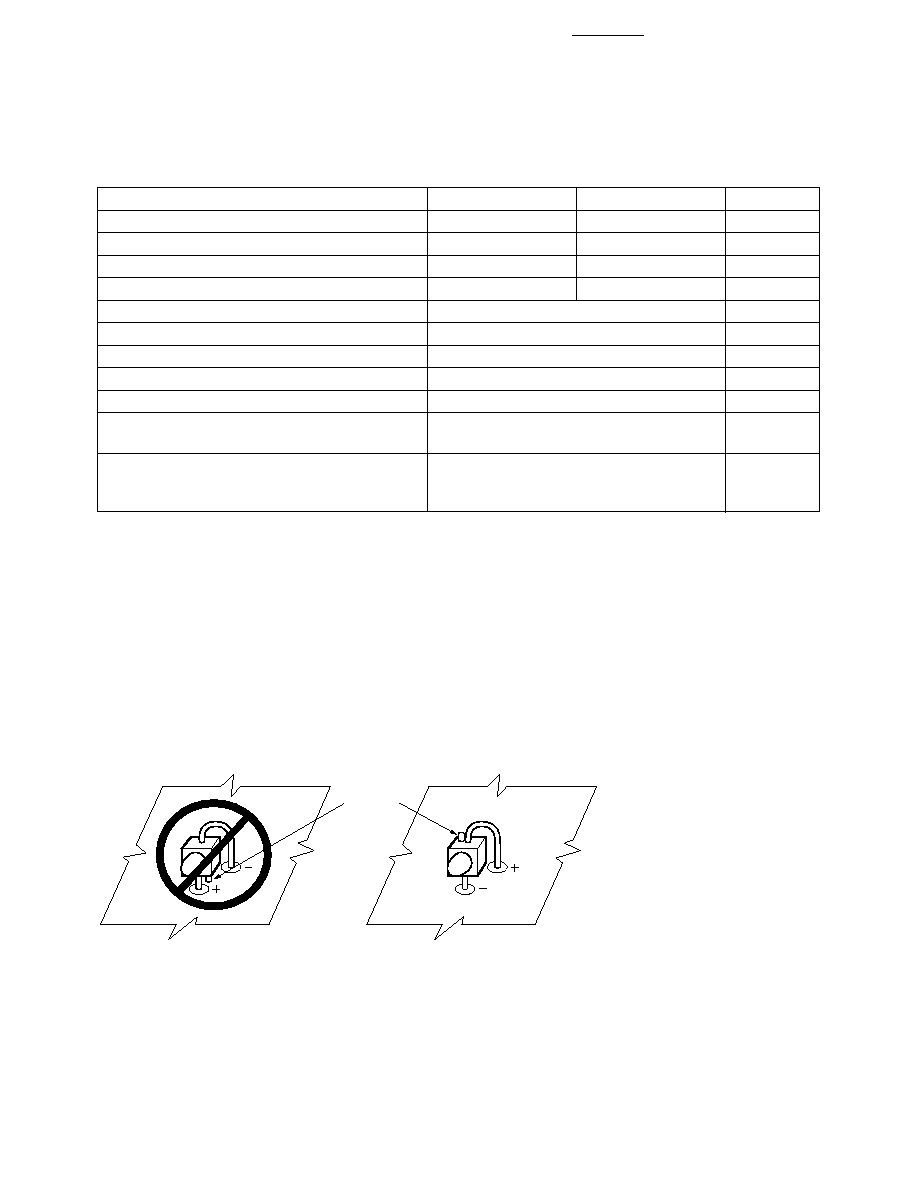
Proper Right Angle Mounting to a PC Board to Prevent Protruding Cathode Tab
from Shorting to Anode Connection.
NO. ANODE DOWN.
YES. CATHODE DOWN.
CATHODE
TAB
Absolute Maximum Ratings at T
A
= 25
∞
C
Parameter
HLMA-xxxx
HLMT-xxxx
Unit
Peak Forward Current
[2]
100
100
mA
Average Forward Current (I
PEAK
= 100 mA)
[1,2]
30
37
mA
DC Forward Current
[3,5,6]
50
50
mA
Power Dissipation
105
120
mW
Reverse Voltage (I
R
= 100
µ
A)
5
V
Transient Forward Current (10
µ
s Pulse)
[5]
500
mA
Operating Temperature Range
≠40 to +100
∞
C
Storage Temperature Range
≠55 to +100
∞
C
LED Junction Temperature
110
∞
C
Lead Soldering Temperature
[1.6 mm (0.063 in.) from body]
260
∞
C for 5 seconds
SMT Reflow Soldering Temperatures
Convective Reflow
235
∞
C Peak, above 183
∞
C for 90 seconds
Vapor Phase Reflow
215
∞
C for 3 minutes
Notes:
1. Maximum I
AVG
at f = 1 kHz.
2. Refer to Figure 5 to establish pulsed operating conditions.
3. Derate linearly as shown in Figure 4.
4. The transient peak current is the maximum non-recurring peak current these devices can withstand without damaging the LED die
and wire bonds. Operation at currents above Absolute Maximum Peak Forward Current is not recommended.
5. Drive currents between 10 mA and 30 mA are recommended for best long term performance.
6. Operation at currents below 5 mA is not recommended, please contact your Agilent sales representative.