Äîêóìåíòàöèÿ è îïèñàíèÿ www.docs.chipfind.ru
Agilent HPMD-7905
FBAR Duplexer for
US PCS Band
Data Sheet
General Description
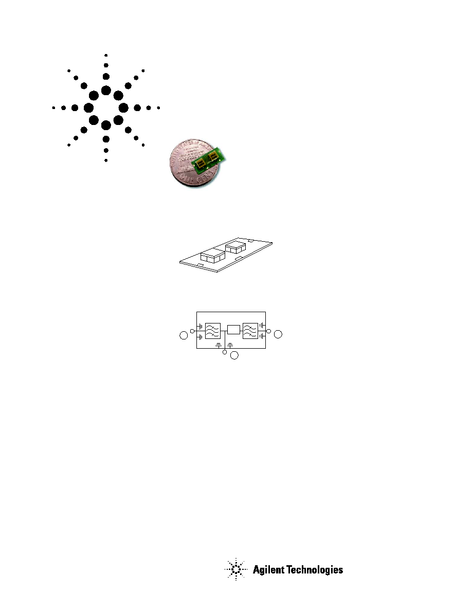
The HPMD-7905 is a miniaturized
duplexer designed for US PCS
handset, designed using Agilent
Technologies' Film Bulk Acoustic
Resonator (FBAR) Technology.
The HPMD-7905 features a very
small size: it is less than 2 mm
thick and has a footprint of only
5.6 x 11.9 mm
2
.
The HPMD-7905 enhances the
sensitivity and dynamic range of
CDMA receivers, providing more
than 49 dB attenuation of
transmitted signal at the receiver
input, and more than 37 dB
rejection of the transmit-
generated noise in the receive
band. Typical insertion loss in
the Tx channel is only 2.5 dB,
minimizing current drain from
the power amplifier. Typical
insertion loss in the Rx channel
is 3.0 dB, improving receiver
sensitivity.
Agilent's thin-Film Bulk Acoustic
Resonator (FBAR) technology
makes possible high-Q filters at a
fraction their usual size. The
excellent power handling of the
bulk-mode resonators supports
the high output powers needed in
PCS handsets, with virtually no
added distortion.
Features
· Miniature size: less than 2 mm high;
5.6 x 11.9 footprint
· Rx Band: 1930-1990 MHz
Typical performance:
Rx noise blocking: 42dB
Insertion loss: 3.0 dB
· Tx Band: 1850-1910 MHz
Typical performance:
Tx interferer blocking: 54dB
Insertion Loss: 2.5 dB
· 30 dBm Tx power handling
Applications
· Handsets or data terminals
operating in the US PCS frequency
band
Board Diagram
Functional Block Diagram
Rx
Ant
2
3
Tx
/4
1
port numbers are circled

2
HPMD-7905 Electrical Specifications, Z
O
= 50
, T
C
[1]
as indicated
+25
°
C
[1,3]
+85
°
C
[1,2,3]
30
°
C
[1,2,3]
Symbol
Parameters
Units
Min
Typ
Max
Min
Max
Min
Max
f
RX
Receive Bandwidth
MHz
1930.6
--
1989.4
1930.6
1989.4
1930.6
1989.4
S23 Rx
Attenuation in Transmit Band
dB
48
--
--
47
--
45
--
(1850.6 1853 MHz)
S23 Rx
Attenuation in Transmit Band
dB
50
54
--
47
--
47
--
(1853 1909.4 MHz)
S23 Rx
Insertion Loss in Receive Band
dB
--
--
3.5
--
3.5
--
4.5
(1930.6 1935 MHz)
S23 Rx
Insertion Loss in Receive Band
dB
--
3.0
3.5
--
3.8
--
3.8
(1935 1987 MHz)
S23 Rx
Insertion Loss in Receive Band
dB
--
--
3.5
--
3.8
--
3.5
(1987 1989.4 MHZ)
S23
Ripple in Receive Band
dB
--
1.5
--
--
--
--
--
S22 Rx
Return Loss in Receive Band
dB
8.0
--
--
8.0
--
8.0
--
f
TX
Transmit Bandwidth
MHz
1850.6
--
1909.4
1850.6
1909.4
1850.6
1909.4
S31 Tx
Attenuation in Receive Band
dB
39
--
--
37.5
--
32.5
--
(1930.6 1931 MHz)
S31 Tx
Attenuation in Receive Band
dB
39
--
--
37.5
--
35
--
(1931 1934 MHz)
S31 Tx
Attenuation in Receive Band
dB
39
42
--
37.5
--
37.5
--
(1934 1987 MHz)
S31 Tx
Attenuation in Receive Band
dB
37.5
--
--
35
--
37.5
--
(1987 1989.4 MHz)
S31 Tx
Insertion Loss in Transmit Band
dB
--
2.5
3.0
--
3.8
--
3.8
(1850.6 1853 MHz)
S31 Tx
Insertion Loss in Transmit Band
dB
--
2.5
3.0
--
3.5
--
3.5
(1853 1907 MHz)
S31 Tx
Insertion Loss in Transmit Band
dB
--
--
3.0
--
3.8
--
3.0
(1907 1909.4 MHz)
S31
Ripple in Transmit Band
dB
--
2.0
--
--
--
--
--
S11 Tx
Return Loss in Transmit Band
dB
8.0
--
--
8.0
--
8.0
--
IP3
Third Order Intercept Point
dBm
--
>60
--
--
--
--
--
S21
Tx-Rx Isolation (1850.6 1860 MHz)
dB
49
--
--
47
--
47
--
S21
Tx-Rx Isolation (1860 1907 MHz)
dB
50
54
--
48
--
47
--
S21
Tx-Rx Isolation (1907 1909.4 MHz)
dB
50
54
--
45
--
48
--
S21
Tx-Rx Isolation (1930.6 1934 MHz)
dB
39
42
--
38
--
35
--
S21
Tx-Rx Isolation (1934 1972 MHz)
dB
39
42
--
38
--
38
--
S21
Tx-Rx Isolation (1972 1975 MHz)
dB
39
42
--
37
--
38
--
S21
Tx-Rx Isolation (1975 1989.4 MHz)
dB
37
--
--
35
--
37
--
Absolute Maximum Ratings
[4]
Parameter
Unit
Value
Operating temperature
[1]
°
C
-30 to +85
Storage temperature
[1]
°
C
-30 to +100
Notes:
1. T
C
is defined as case temperature, the temperature of the underside of the duplexer where it
makes contact with the circuit board.
2. Specifications are given at operating temperature limits and room temperature. To estimate
performance at some intermediate temperature, use linear interpolation.
3. Specifications are guaranteed over the given temperature range, with the input power to the Tx
port equal to +30 dBm (or lower) over all Tx frequencies. The application of input power levels in
excess of +30 dBm will not destroy the duplexer, but its performance may exceed the specification
limits given above.
4. Operation in excess of any one of these conditions may result in permanent damage to the device.
3
0
-10
-20
-30
-40
-50
-60
-70
INSERTION LOSS AND REJECTION (dB)
1.82
1.84
1.86
1.88
1.90
1.92
1.94
1.96
2.00
1.98
2.02
FREQUENCY (GHz)
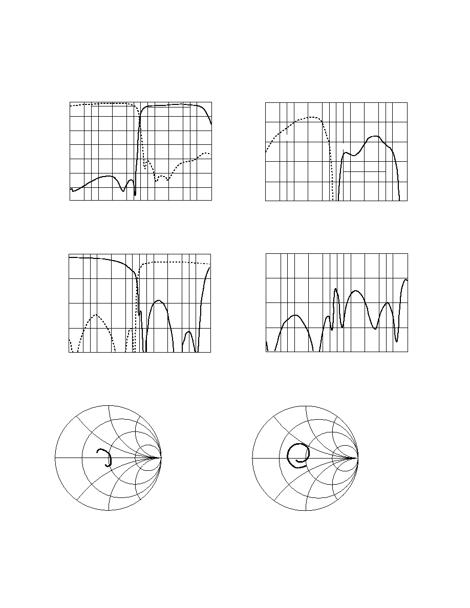
Figure 1. Tx and Rx Port Insertion Loss (typical).
S
31
S
23
0
-1
-2
-3
-4
-5
INSERTION LOSS AND REJECTION (dB)
1.82
1.84
1.86
1.88
1.90
1.92
1.94
1.96
2.00
1.98
2.02
FREQUENCY (GHz)
Figure 2. Insertion Loss Detail (typical).
S
31
S
23
0
-5
-10
-15
-20
RETURN LOSS (dB)
1.82
1.84
1.86
1.88
1.90
1.92
1.94
1.96
2.00
1.98
2.02
FREQUENCY (GHz)
S
11
S
22
Figure 3. Tx and Rx Port Return Loss (typical).
0
-5
-10
-15
-20
RETURN LOSS (dB)
1.82
1.84
1.86
1.88
1.90
1.92
1.94
1.96
2.00
1.98
2.02
FREQUENCY (GHz)
S
33
Figure 4. Ant Port Return Loss (typical).
freq (1.850 GHz to 1.910 GHz)
Figure 5. S11, Tx Port Impedance (typical).
The plots below provide typical
performance obtained from
samples of the HPMD-7905
duplexer.
In order to obtain the best
performance from the
HPMD-7905 duplexer, refer to
Design Note D007, which is
available from your Agilent
Technologies technical support
or sales departments.
freq (1.930 GHz to 1.990 GHz)
Figure 6. S22, Rx Port Impedance (typical).
4
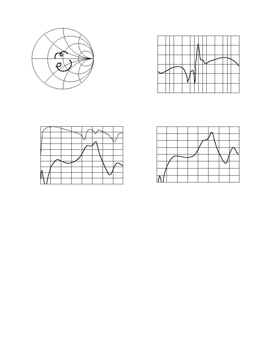
A: freq (1.850 GHz to 1.910 GHz)
B: freq (1.930 GHz to 1.990 GHz)
Figure 7. S33, Ant Port Impedance.
A
B
-20
-30
-40
-50
-60
-70
-80
ISOLATION (dB)
1.82
1.84
1.86
1.88
1.90
1.92
1.94
1.96
2.00
1.98
2.02
FREQUENCY (GHz)
Figure 8. S21, Isolation (typical).
S
21
0
-5
-10
-15
-20
-25
-30
-35
-40
-45
-50
RETURN LOSS (dB)
2.0
2.5
3.0
3.5
4.0
4.5
5.0
5.5
6.0
FREQUENCY (GHz)
Figure 9. Wideband Insertion Loss (typical).
S
31
S
23
-10
-15
-20
-25
-30
-35
-40
-45
-50
ISOLATION (dB)
2.0
2.5
3.0
3.5
4.0
4.5
5.0
5.5
6.0
FREQUENCY (GHz)
Figure 10. Wideband Isolation (typical).
S
21
5
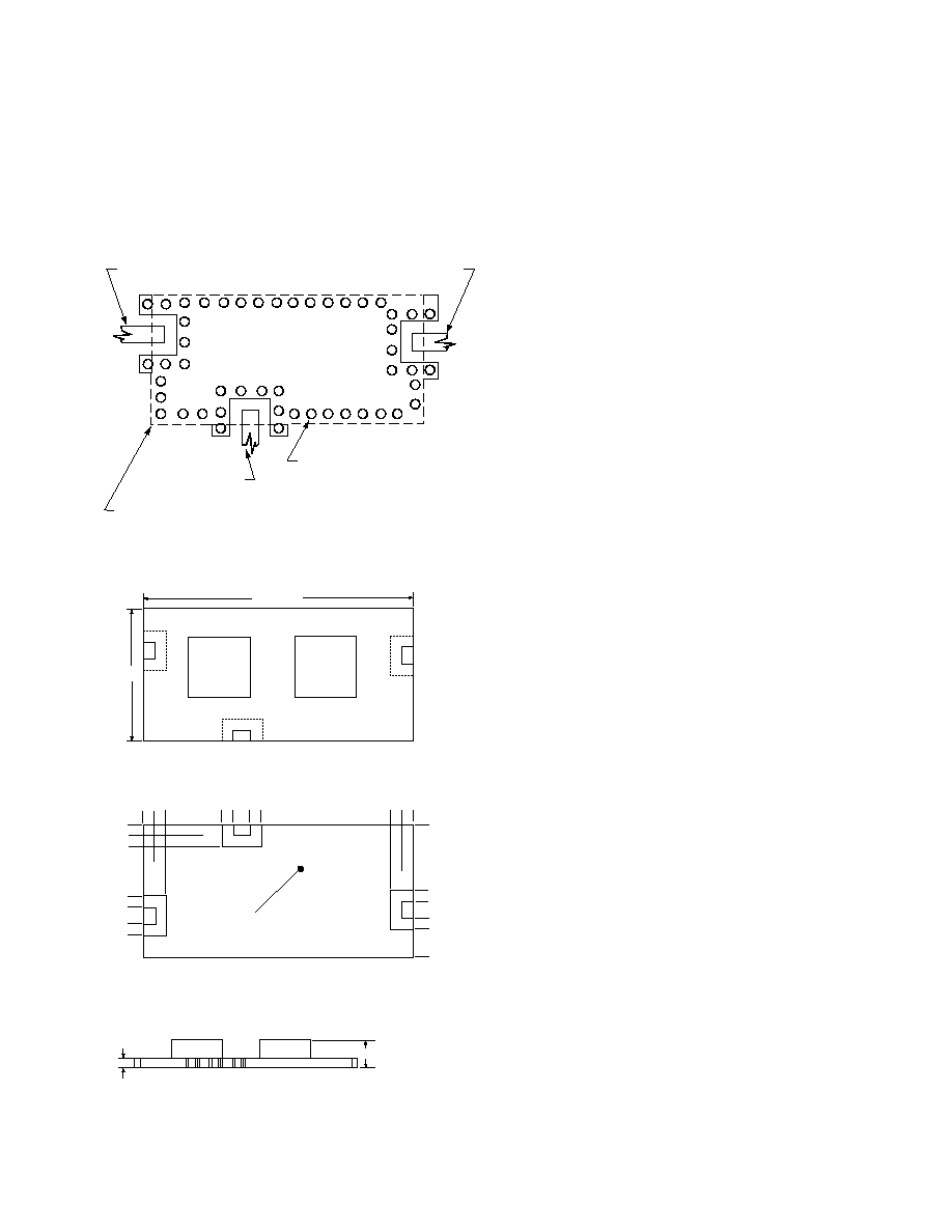
Note that the specifications given
on page 2 are guaranteed when
the duplexer is mounted on a
ground surface with a hole
pattern like that one shown in
Figure 11. See Design Note D007,
Figure 11. Mounting (grounding) Pattern.
0.4 mm diameter plated through holes
typical spacing is 0.77 to 0.9 mm
Rx output
Ant input/output
Duplexer outline shown in dashed line
Tx input
Figure 12. Outline Drawing.
which is available from your
Agilent Technologies technical
support or sales departments.
Note that it is important that
proper heat sinking be provided
in order to remove the heat
generated in the Tx filter by the
handset's power amplifier.
Failure to do so may result in
excessive losses, especially at the
top end of the Tx band.
0
2.61
10.86
5.14
4.63
3.87
3.36
1.02
0.51
0
0.51
1.02
3.0
3.49
4.26
4.76
0
11.37
11.88
±
0.1
3.12
3.88
4.39
5.62
±
0.1
Solid ground plane
BOTTOM VIEW
SIDE VIEW
Pin Number/Description
1 Tx Port
3 Ant Port
2 Rx Port
4 Ground
Note:
All dimensions in millimeters.
3
4
2
1
Rx Filter
Tx Filter
Port1
Tx
Port3
Ant
Port2
Rx
11.88
±
0.1
5.63
±
0.1
TOP VIEW
1.9 Max
0.29
±
0.1
Document Outline
- HPMD-7905
- General Description
- Board Diagram
- Functional Block Diagram
- Features
- Applications
- Electrical Specifications
- Absolute Maximum Ratings
- Typical Performance
- Mounting Pattern
- Outline Drawing
- Tape Drawing
- Reel Drawing
- Device Orientation
- Solder Recommendations
- Recommended Solder Profile
- Part Number Ordering Information