Agilent HSMx-C177, HSMx-C197
Low Profile Chip LEDs
Data Sheet
Features
∑ Small size with extremely low
profile
∑ 0805 or 0603 industry standard
footprint with 0.4 mm height
∑ Diffused optics
∑ Operating temperature range of
≠30
∞
C to +85
∞
C
∑ Compatible with IR soldering
∑ Available in 7 colors
∑ Available in 8 mm tape on 7"
diameter reel
∑ Reel sealed in zip locked
moisture barrier bags
Applications
∑ Membrane switch indicator
∑ LCD backlighting
∑ Push button backlighting
∑ Front panel indicator
∑ Symbol backlighting
∑ Keypad backlighting
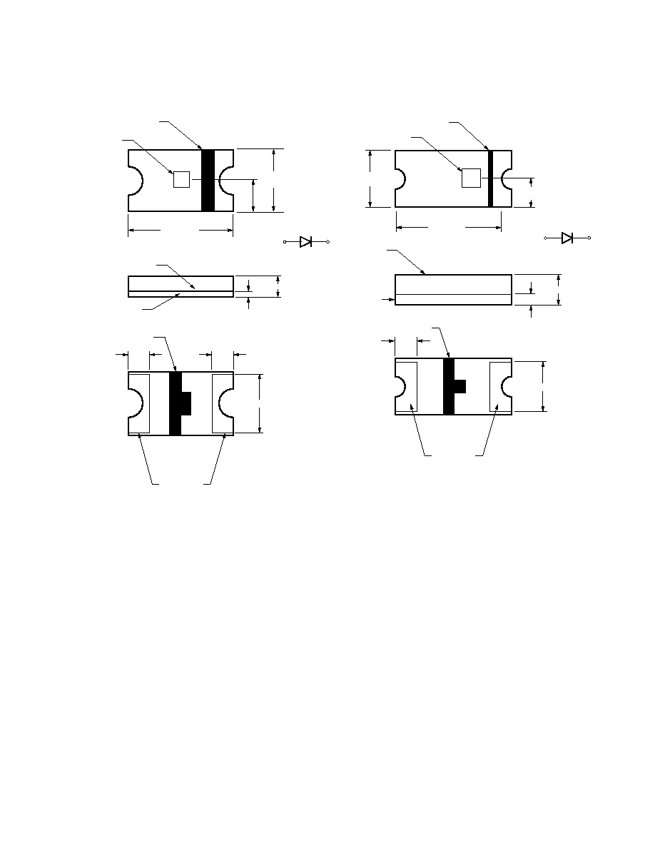
Description
The HSMx-C177 and HSMx-C197
ChipLEDs are designed specifically
for the membrane switch applica-
tion. The request is to have the
height as low as possible while re-
taining the footprint at the optimal
size of a 0805 (2.0 x 1.25 mm) or
0603 (1.6 x 0.8 mm) device. Apart
from the membrane switch applica-
tion, the HSMx-C177 is also suit-
able for use in applications where
low height is required.
Seven different colors are avail-
able: green, red, yellow, orange,
deep red, blue, and amber. All
parts are intensity binned and
color binned (except for red
color). They come in 8 mm tape
on a 7 inch diameter reel with
4000 units per reel which makes
them compatible for automatic
placement.
Device Selection Guide
AS AlInGaP
Product Number
Color
Package Description
HSMA-C177/C197
Amber
Untinted, Diffused
HSMT-C177/C197
Deep Red
Untinted, Diffused
HSMC-C177/C197
Red
Untinted, Diffused
HSML-C177/C197
Orange
Untinted, Diffused
GaP
Product Number
Color
Package Description
HSMG-C177/C197
Green
Untinted, Diffused
HSMD-C177/C197
Orange
Untinted, Diffused
HSMS-C177/C197
HER
Untinted, Diffused
HSMY-C177/C197
Yellow
Untinted, Diffused
InGaN
Product Number
Color
Package Description
HSMQ-C177/C197
Green
Untinted, Diffused
HSMR-C177/C197
Blue
Untinted, Diffused
3
Absolute Maximum Ratings at T
A
= 25∞C
HSMA/C/L-C177/C197,
Parameter
HSMT-C177/C197
HSMG/D/S/Y-C177/C197
HSMQ/R-C177/C197
Units
DC Forward Current
[1]
25
20
20
mA
Peak Pulsing Current
[2]
100
100
100
mA
Power Dissipation
64
54
78
mW
Reverse Voltage (I
R
= 100
µ
A)
5
5
5
V
LED Junction Temperature
95
95
95
∞C
Operating Temperature Range
≠30 to +85
≠30 to +85
≠30 to +85
∞C
Storage Temperature Range
≠40 to +85
≠40 to +85
≠40 to +85
∞C
Soldering Temperature
See IR soldering profile (Figure 7)
Notes:
1. Derate linearly as shown in Figure 4.
2. Pulse condition of 1/10 duty and 0.1 ms width.
Electrical Characteristics at T
A
= 25∞C
Forward Voltage
Reverse Breakdown
Capacitance C
Thermal
V
F
(Volts)
V
R
(Volts)
(pF), V
F
= 0,
Resistance
@ I
F
= 20 mA
@ I
R
= 100
µ
A
f = 1 MHz
R
J≠PIN
(∞C/W)
Part Number
Typ.
Max.
Min.
Typ.
Typ.
HSMA-C177/197
1.9
2.4
5
11
300
HSMC-C177/197
1.9
2.4
5
15
300
HSML-C177/197
1.9
2.4
5
20
300
HSMT-C177/197
1.9
2.4
5
15
300
HSMG-C177/197
2.2
2.6
5
9
250
HSMD-C177/197
2.2
2.6
5
7
250
HSMS-C177/197
2.1
2.6
5
5
250
HSMY-C177/197
2.1
2.6
5
6
250
HSMQ-C177/197
3.4
3.9
5
110
350
HSMR-C177/197
3.4
3.9
5
110
350
V
F
Tolerance:
±
0.1 V
4
Optical Characteristics at T
A
= 25∞C
Luminous
Color,
Viewing
Luminous
Intensity
Peak
Dominant
Angle
Efficacy
I
V
(mcd)
Wavelength
Wavelength
2
1/2
V
@ 20 mA
[1]
peak
(nm)
d
[2]
(nm)
Degrees
[3]
(lm/w)
Part Number
Color
Min.
Typ.
Typ.
Typ.
Typ.
Typ.
HSMA-C177/197
AS Amber
25
90
595
592
130
480
HSMC-C177/197
AS Red
25
90
637
626
130
155
HSML-C177/197
AS Orange
25
90
609
605
130
370
HSMT-C177/197
AS Deep Red
10
30
660
639
130
70
HSMG-C177/197
GaP Green
4.0
15
570
572
130
595
HSMD-C177/197
GaP Orange
2.5
8
605
604
130
380
HSMS-C177/197
HER
2.5
10
630
626
130
145
HSMY-C177/197
GaP Yellow
2.5
8
589
586
130
500
HSMQ-C177/197
InGaN Green
40
145
520
527
130
510
HSMR-C177/197
InGaN Blue
16
55
469
473
130
88
Notes:
1. The luminous intensity, I
V
, is measured at the peak of the spatial radiation pattern which may not be aligned with the mechanical axis of the lamp package.
2. The dominant wavelength,
d
, is derived from the CIE Chromaticity Diagram and represents the perceived color of the device.
3.
1/2
is the off-axis angle where the luminous intensity is 1/2 the peak intensity.
Color Bin Limits
Green Color Bins
[1]
Dom. Wavelength (nm)
Bin ID
Min.
Max.
A
561.5
564.5
B
564.5
567.5
C
567.5
570.5
D
570.5
573.5
E
573.5
576.5
Tolerance:
±
0.5 nm
Blue Color Bins
[1]
Dom. Wavelength (nm)
Bin ID
Min.
Max.
A
460.0
465.0
B
465.0
470.0
C
470.0
475.0
D
475.0
480.0
Tolerance:
±
1 nm
5
Light Intensity (Iv) Bin Limits
[1]
Intensity (mcd)
Bin ID
Min.
Max.
A
0.11
0.18
B
0.18
0.29
C
0.29
0.45
D
0.45
0.72
E
0.72
1.10
F
1.10
1.80
G
1.80
2.80
H
2.80
4.50
J
4.50
7.20
K
7.20
11.20
L
11.20
18.00
M
18.00
28.50
N
28.50
45.00
P
45.00
71.50
Q
71.50
112.50
R
112.50
180.00
S
180.00
285.00
T
285.00
450.00
U
450.00
715.00
V
715.00
1125.00
W
1125.00
1800.00
X
1800.00
2850.00
Y
2850.00
4500.00
Note:
1. Bin categories are established for classifica-
tion of products. Products may not be avail-
able in all categories. Please contact your
Agilent representative for information on
currently available bins.
Yellow/Amber Color Bins
[1]
Dom. Wavelength (nm)
Bin ID
Min.
Max.
A
582.0
584.5
B
584.5
587.0
C
587.0
589.5
D
589.5
592.0
E
592.0
594.5
F
594.5
597.0
Orange Color Bins
[1]
Dom. Wavelength (nm)
Bin ID
Min.
Max.
A
597.0
600.0
B
600.0
603.0
C
603.0
606.0
D
606.0
609.0
E
609.0
612.0
F
612.0
615.0
InGaN Green Color Bins
[1]
Dom. Wavelength (nm)
Bin ID
Min.
Max.
A
515.0
520.0
B
520.0
525.0
C
525.0
530.0
D
530.0
535.0
Tolerance:
±
0.5 nm
Tolerance:
±
1 nm
Note:
1. Bin categories are established for classification of products. Products may not be available in all
categories. Please contact your Agilent representative for information on currently available bins.
Tolerance:
±
1 nm
Tolerance:
±
15%