Document Outline
- Features
- Applications
- Description
- Pin Connections
- Mechanical Outline
- LSC2110-622 Typical Operating Characteristics
- Absolute Maximum Ratings
- Performance Specification
- Fiber Pigtail: Tight jacketed, self-mode stripping, single mode fiber
- Ordering Information
- Handling Precautions
- CDRH Certification
- Laser Warning
468
Laser Safety Warning
This device is a Class IIIb (3b) Laser Product. It may emit invisible laser radiation if operated with the fiber pigtail disconnected. To avoid
possible eye damage do not look into an unconnected fiber pigtail during laser operation. Do not exceed specified operating limits.
Features
∑ 2.5 Milliwatt Peak Optical
Power Output
∑ Center Wavelength between
1294 nm and 1329 nm
∑ Narrow Linewidth: <1.7 nm
∑ Modulation Bandwidth:
>1 Ghz
∑ Wide Operating Tempera-
ture Range: -40
∞
C to +85
∞
C
∑ Industry Standard Hermetic
14 Pin Dual-In-Line Package
Applications
∑ 622 Mbit/s SONET/SDH
∑ Local Area and Metropolitan
Area Networks
∑ Point-to-Point Data
Communications
∑ Fiber Optic Sensors
∑ Cable Television
∑ Military Communications
and Control Systems
∑ Instrumentation
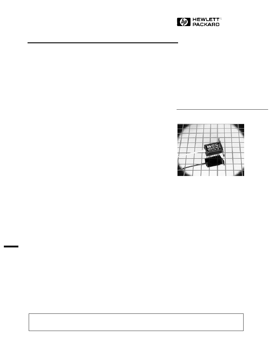
2.5 mW 14 Pin DIL Cooled Laser
Module
Technical Data
LSC2110-622
Description
LSC2110-622 laser modules are
highly reliable fiber optic light
sources operating in the 1300
nanometer band. The internal
semiconductor lasers are based
upon InGaAsP buried hetero-
structure (BH) technology and
fabricated by the Metal Organic
Vapor Phase Epitaxy (MOVPE)
process, resulting in long
lifetimes and modest threshold
currents.
LSC2110-622 package includes a
photodiode for monitoring the
laser output, a thermistor for
monitoring the laser submodule
temperature and a Peltier effect
thermoelectric cooler (TEC). A
heatsink mounting flange is
incorporated into the industry
standard 14 pin package.
The LSC2110-622 has been
specifically designed to meet the
requirements of STM4.1 and
SONET OC12 LR1 applications.
5962-9398E (1/95)
469
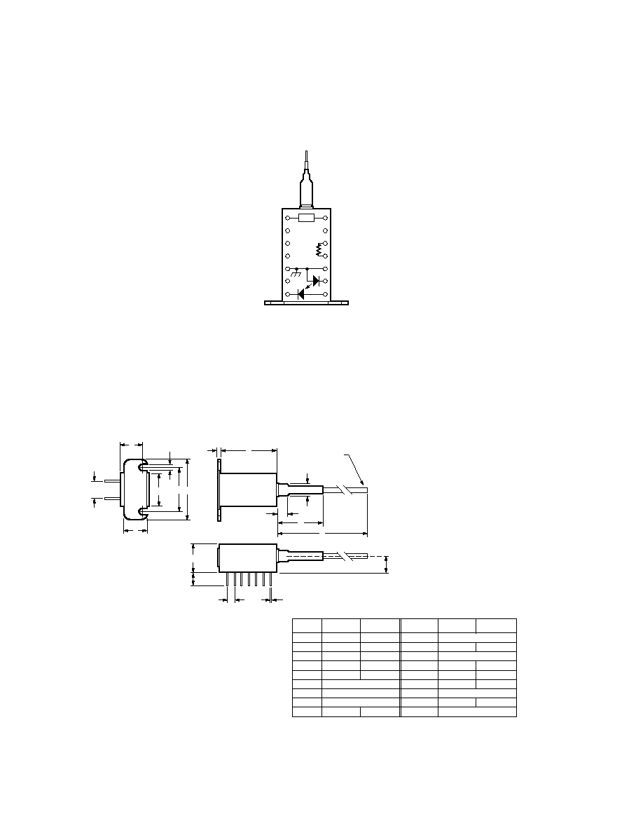
Pin Connections
Top View
Mechanical Outline
TEC
14 TEC CATHODE (-ve SUPPLY TO COOL)
13 NOT CONNECTED
12 THERMISTOR
11 THERMISTOR
10 LASER ANODE (+ve SUPPLY) CASE GROUND
9 LASER CATHODE (-ve SUPPLY)
8 MONITOR PHOTODIODE ANODE (-ve SUPPLY)
TEC ANODE (+ve SUPPLY TO COOL) 1
NOT CONNECTED 2
NOT CONNECTED 3
RESERVED - DO NOT CONNECT 4
CASE GROUND 5
RESERVED - DO NOT CONNECT 6
MONITOR PHOTODIODE CATHODE (+ve SUPPLY) 7
R
G
E
D
B
FIBER PIGTAIL
A
P
T
M
F
U
J
C
K L
S
N
H
DIM.
MIN.
MAX.
A
B
C
D
E
F
G
H
J
20.68
0.90
12.55
8.51
6.10
7.62 NOM.
2.54 NOM.
0.457 NOM.
7.01
20.98
1.10
13.00
9.60
6.60
7.21
ALL DIMENSIONS IN MILLIMETERS
DIM.
MIN.
MAX.
K
L
M
N
P
R
S
T
U
19.05 NOM.
25.10
30.00 NOM.
≠
1000
5.80
6.00 NOM.
≠
3.17 NOM.
25.70
4.20
≠
6.20
6.00
470
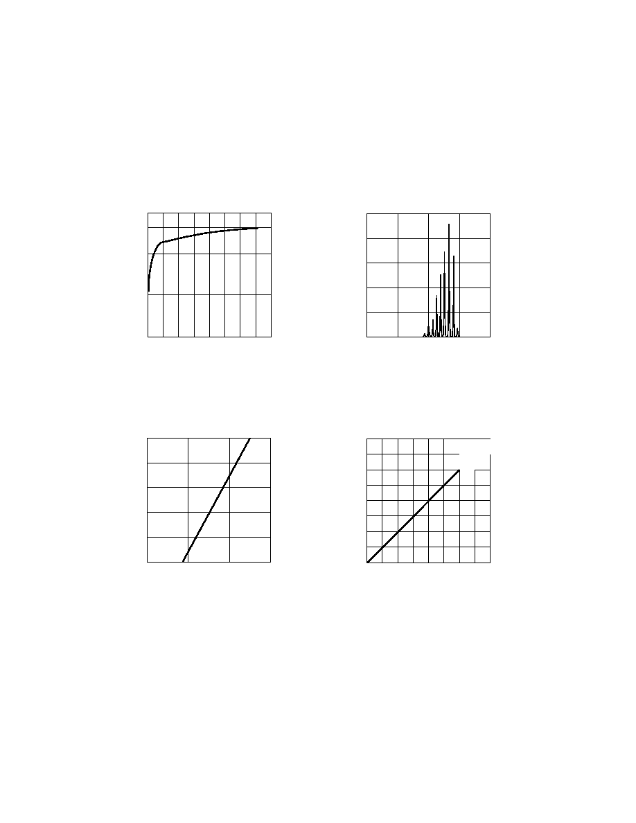
LSC2110-622 Typical Operating Characteristics
RELATIVE POWER
WAVELENGTH (nm)
1315
60
100
1300
1305
40
1310
SPECTRAL CONTENT
80
20
0
OUTPUT POWER (mW)
0
FORWARD CURRENT (mA)
60
1.5
2.5
20
40
1.0
OUTPUT POWER
vs. FORWARD CURRENT
2.0
0.5
0
FORWARD VOLTAGE (V)
0
FORWARD CURRENT (mA)
80
1.0
50
1.2
30
20
10
40
70
0.5
60
LASER FORWARD VOLTAGE
vs. FORWARD CURRENT
MONITOR DIODE PHOTOCURRENT (µA)
0
OUTPUT POWER (mW)
4.0
500
800
1.5
2.5
300
MONITOR PHOTOCURRENT
vs. OUTPUT POWER
600
100
0
0.5 1.0
2.0
3.0 3.5
700
400
200
471
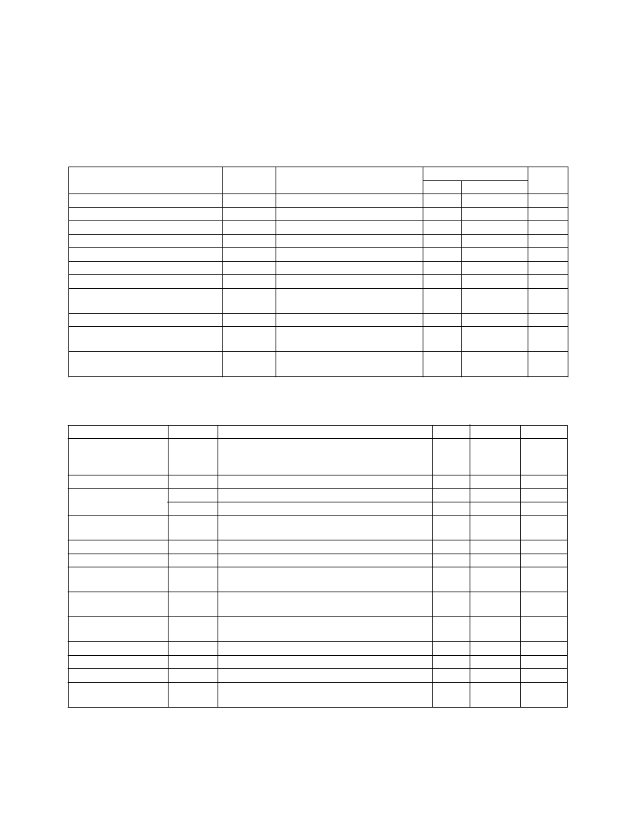
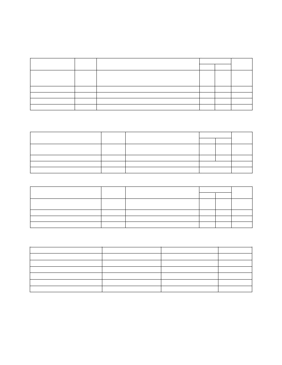
Absolute Maximum Ratings
Absolute maximum limits mean that no catastrophic damage will occur if the product is subjected to these ratings for short periods, provided
each limiting parameter is in isolation and all other parameters have values within the performance specification. It should not be assumed that
limiting values of more than one parameter can be applied to the product at the same time.
Limits
Parameter
Symbol
Conditions
Min.
Max.
Units
Laser Forward Current
If
DC
-
150
mA
Laser Reverse Current
Ir
DC
-
100
µ
A
Laser Reverse Voltage
Vlr
DC
-
2
V
Photodiode Reverse Voltage
Vr
DC
-
10
V
Photodiode Forward Current
Ipf
DC
-
1
mA
Operating Temperature
Tc
Pf min.
-40
+85
∞
C
Storage Temperature
Ts
-40
+85
∞
C
Relative Humidity
RH
0.0
non-
%RH
condensing
Fiber Pull Strength
-
10
N
Mechanical Shock
Mil Std 883, Method 2002,
Condition A
Vibration
Mil Std 883, Method 2007,
Condition A
Performance Specification
Parameter
Symbol
Test Conditions
Min.
Max.
Units
LASER
Tc = -40
∞
C to +85
∞
C,
T = +65
∞
C (heating)
T = -40
∞
C (cooling), CW, Pf = 2.5 mW
unless otherwise stated
Threshold Current
Ith
5
25
mA
Peak Optical
Pf
2.5
-
mW
Output Power
Pf
4
-
dBm
Optical Output
Pth
Pth = Pf @ Ith -2 mA
-
50
µ
W
Power
Slope Efficiency
Tc = 25
∞
C, Rt = 10 k
0.05
0.12
mW/mA
Forward Voltage
Vf
-
1.8
V
Differential
Rd
dV/dI
-
10
Resistance
Centre Wavelength
c
Mod @ 622 Mbit/s, 50% duty cycle,
1294
1329
nm
ORL 20 dB
c Change with
c/
T
From Tc = 65
∞
C to 85
∞
C,
T = -40
∞
C
-
0.5
nm/
∞
C
Temperature
Spectral Width
Modulated as for
c, 1 x
, RMS
-
1.7
nm
Rise Time
r
10% to 90%: Ith to Pf = 2.5 mW
-
0.4
ns
Fall Time
f
90% to 10%: Pf = 2.5 mW to Ith
-
0.4
ns
Small Signal
Bw
±
3 dB
1.0
-
GHz
Freq. Response
472
Performance Specifications (cont'd.)
Ratings
Parameter
Symbol
Test Conditions
Min.
Max.
Units
MONITOR
Tc = -40
∞
C to +85
∞
C,
T = +65
∞
C (heating)
PHOTODIODE
T = -40
∞
C (cooling), CW, Pf = 2.5 mW
Vr = 5 V (Note 1), unless otherwise specified
Photocurrent
Im
0.1
2.0
mA
Responsivity
R
0.04
0.8
A/W
Dark Current
Id
Pf = 0 mW, Tc = ~25
∞
C, Rt = 10 k
-
20
nA
Tracking Error
R
Im = Im @ (Pf = 2.5 mW, Tc = 25
∞
C)
-
±
0.5
dB
Note:
1. Monitor Photodiode will also operate under zero bias conditions.
Fiber Pigtail:
Tight jacketed, self-mode stripping, single mode fiber
Parameter
Minimum
Maximum
Units
Length
1.0
-
m
Spot Size (Mode Radius)
4.5
5.5
µ
m
Cladding Diameter
122
128
µ
m
Core/Cladding Concentricity
-
1.0
µ
m
Secondary Jacket Diameter
0.8
1.0
mm
Effective Cutoff Wavelength
1150
1240
nm
Ratings
Parameter
Symbol
Test Conditions
Min.
Max.
Units
THERMISTOR
Tc = 25
∞
C, unless otherwise
specified
Resistance
Rt
9.5
10.5
k
Temperature Coefficient of Rt
Rt/
T
Typ -4.4
%dR/
∞
C
Constant
0
∞
C to 50
∞
C
Typ 3900
∞
K
Ratings
Parameter
Symbol
Test Conditions
Min.
Max.
Units
TEC
Pf = 2.5 mW, unless otherwise
specified
TEC Cooling Current
Ic
T = -40
∞
C, Tc = 85
∞
C
-
1.0
A
TEC Heating Current
Ih
T = 65
∞
C, Tc = -40
∞
C
-
1.0
A
Voltage
Vc
T = -40
∞
C to 65
∞
C
-
2.0
V