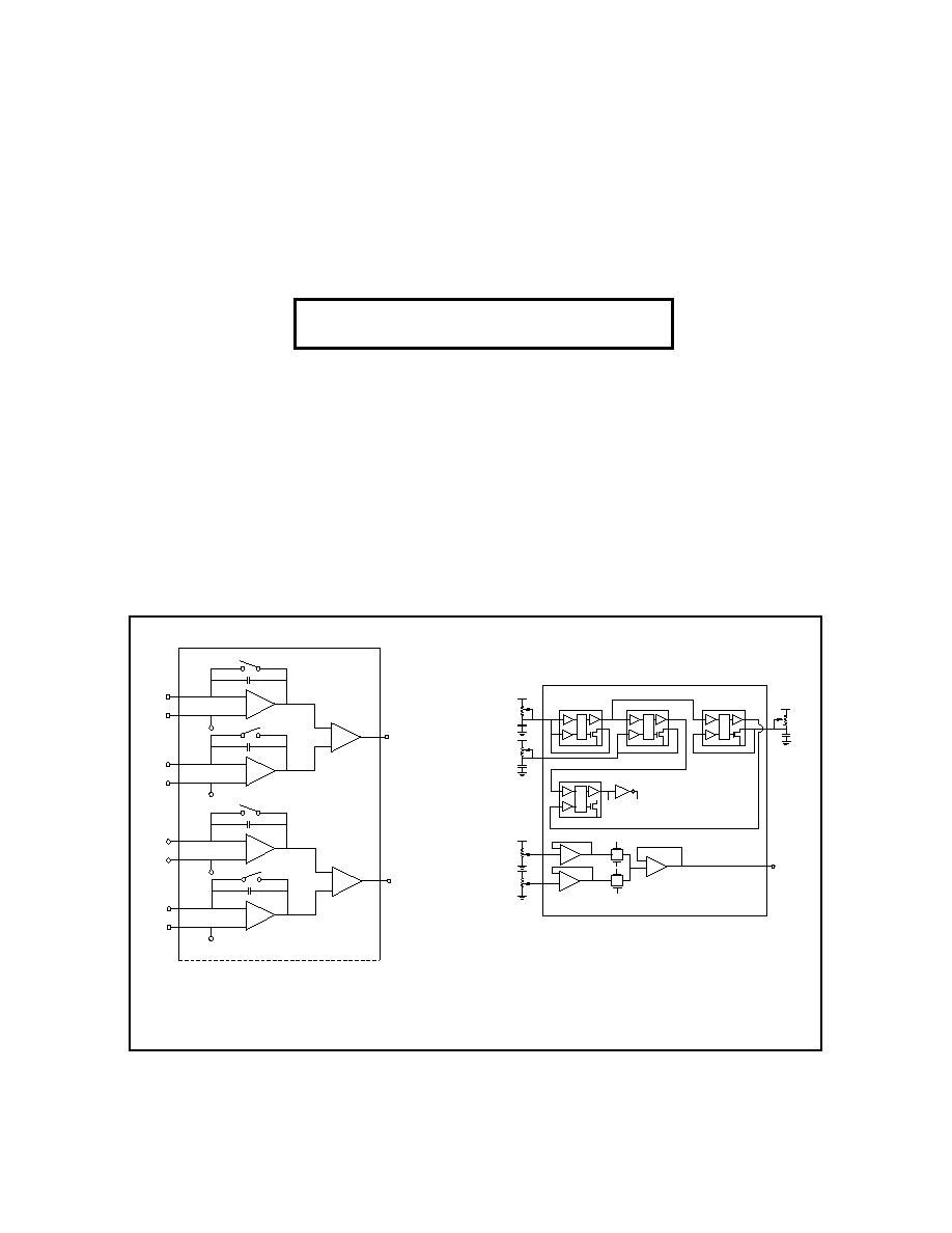
EXAMPLE 1. 1/2 of OCTAL INTEGRATOR
415 Tasman Drive
Sunnyvale, California 94089-1706
Telephone: 408/747-1155
Fax: 408/747-1286
http:\www.aldinc.com
A PRACTICAL SOLUTION to CUSTOM LINEAR I.C.'s --
ALD's "FUNCTION-SPECIFIC" ASIC PROGRAM
"FUNCTION-SPECIFIC" is ALD's standard cell approach to custom linear circuits with the standard cells being ALD
standard products. It allows you to design with completely specified standard linear I.C.'s and implement your custom
I.C. - or - go into production with standard I.C.'s and transition into your custom I.C. - with no redesigns - as your
production volume increases.
Standard Part = Standard Cell = Kit Part
Easy to implement.
Step I. Order your "Function-Specific" Design Kit.
Step II. Design your circuit with ALD standard products.
Step III. Breadboard and prove your design.
Step IV. Decide on the package and pin-out.
Step V. Send your circuit to ALD for a quotation.
Step VI. Place order, wait 12 -16 weeks, and receive your
"Function-Specific" Circuit.
No I.C. design techniques or software to learn. A full custom, high performance ASIC Program. There is a nonrecurring
engineering charge. All standard packages, including SOIC's and dice, are available. Hi Rel processing available.
Examples of "FUNCTION-SPECIFIC" Linear I.C.'s
EXAMPLE 2. RAIL TO RAIL PULSE GENERATOR
( Consists of 3 Op Amps, 4 Timers,
4 MOSFETS and 74C04 Inverter )
(Consists of 8 Op Amps, 4 Comparators,
8 MOSFETS and 8 Capacitors)
ALD1704
ALD1704
ALD1704
ALD1704
ALD1502
A
A
A
B
B
B
ALD1101/ALD 1102
ALD1704
74CO4
R
S
VDD
VDD
VO1
VO2
50K
50K
CLOCK LOW LEVEL
ADJUST
CLOCK HIGH LEVEL
ADJUST
ALD1502
ALD1502
FREQUENCY
ADJUST
50K
50K
10nF
1nF
PULSE
DELAY
ADJUST
R
R
R
S
S
S
50K
10nF
PULSE WIDTH
ADJUST
OUTPUT
ALD1502
C
C
+
_
+
_
C = 25 pF
OP AMP
1702
OP AMP
1702
+2.5 V
+2.5 V
+2.5 V
+2.5 V
OP AMP
1702
OP AMP
1702
ALD1101
C
C
ALD1102
ALD1101
ALD1102
COMPARATOR
COMPARATOR
1/2 2301
1/2 2301
C
C

Packaging, Hi Rel, and Non-Standard Cells
�
Your packaging requirements are met with industry standard PDIP, CDIP, SOIC, PLCC, and DICE. Standard pin
counts are 8, 14, 16, 18, 20, 22, 24, 28, 40, 48, 54, 68 and 84. Special packages are available.
�
High reliability military processing is available, as is ALD's industrial enhanced reliability "A+" program.
�
New products (=standard cells) are continually being announced by ALD. Should your design require cells not
currently announced, check with us to see if what we have coming fits in with your plans. In the event ALD's
"Function-Specific" approach doesn't meet your needs, ALD will work with you on your "full-custom I.C."
What is ALD's "FUNCTION-SPECIFIC" Approach?
�
No I.C. design techniques or software to learn. Optional simulation models, macromodels and subcircuits are
available.
�
Design and breadboard with completely specified, off the shelf, standard I.C.'s as you normally do.
�
Minimizes risk - proves your design works before committing to a custom chip.
�
If you're not sure your volume justifies a custom chip just yet, go into production with standard ALD linear I.C.'s
and transition to a custom I.C. when it suits you -AND- without a major redesign.
�
Optimizes your surface mount program - use an SOIC package and combine your linear I.C.'s onto one chip.
�
FAST: 12-16 weeks is the normal lead time once your "Function-Specific" order is placed -AND- you don't have to
spend weeks or months becoming an I.C. designer in order to develop your circuit.
�
Low power, low voltage, precision Silicon Gate CMOS - using ALD's precision ACMOS process - provides 5V
linear I.C.'s that match-up with the 5V digital circuits you're using in today's low voltage, low power systems.
How Does ALD's "Function-Specific" Design Approach Compare?
COMPARISON OF VARIOUS DESIGN APPROACHES
Relative Comparison Scale of 0 to 10
_______________________________________________________________________________________
Full
"Function-
Cell
Linear
Standard
Customl
Specific"
Library
Array
Product
ASIC
ASIC
ASIC
_______________________________________________________________________________________
Circuit Performance
10
10
7
5
10
I.C. Design Cost
10
2
2
2
0
Design & Prototype Ease
1
10
3
3
10
Prototype Development Time
10
5
5
3
0
Die Size Optimization
10
7
7
5
NA
Project Cost
10
2
3
2
0
First Time Prototype
4
10
7
5
NA
Success Rate
Redesign Flexibility
4
10
7
5
10
Test Engineering Cost
10
2
5
8
0
Production Unit Cost
3
3
7
10
2
Per Function Reliability
10
10
5
5
2
P C Board Cost
1
1
2
2
5
Production Cost
1
2
2
2
5
Design Security
10
8
8
8
1
Ease of Field Testing
1
10
2
2
10
Production Quantity Time
10
4
4
4
2

Op amps with:
� Rail to Rail inputs and outputs
� 10
12
input impedance
� Dual or single supply
� Low power, low voltage
Timers/Oscillators with:
� 99% accuracy
� Up to 1.4 to 2.5 MHz frequency
� 1V to 12V supply voltage
� Low power
Comparators with:
� Response times of 120ns to 650ns
� Output current of 24mA to 60mA
� Low power: 55
�
A to 250
�
A
� 10
12
input impedance
� Low voltage, dual or single supply
MOSFET Pairs with:
� N channel and P channel
� Low voltage, low power
Next page shows a summary. See individual data sheets for complete specifications.
Frequently Asked Questions Regarding "Function-Specific" Circuits
Q: Is this like a linear array?
A: No. An array is a chip filled with fixed transistors, diodes and passives - which you must design with and intercon-
nect - following I.C. design rules and sometimes using specialized software and hardware. "Function-Specific" is a
standard cell approach with defined I.C.'s (standard parts) you configure using your standard design practices,
resulting in a completely custom chip. In "Function-Specific" you have completely characterized higher level
building blocks (such as various operational amplifiers) that were carefully developed to be integrated.
Q: What about critical nodes? Will my circuit work in chip form?
A: ALD has already solved this problem. The critical nodes are within the devices themselves - inside the op amps,
timers, comparators, etc. All the normal input, output, and power supply nodes are noncritical and designed to
withstand parasitic stray capacitances. As a result, integrating a variety of devices on a single chip presents no
particular problem - as long as the breadboard works.
Q: Is "SPICE" available for simulation?
A: ALD supports simulation models, subcircuits and macromodels. PSPICE with this simulation can be conducted by
either a customer or by ALD personnel, as a supplement to the breadboard.
Q: Why does it take 12-16 weeks?
A: Because each I.C. is different and must have a unique, complete custom mask set generated, wafers fabricated and
tested, units packaged, final tested, and shipped.
Q: Can resistors and capacitors be integrated in a "Function-Specific" I.C.?
A: Yes, resistors and capacitors can be integrated on your custom linear I.C.
Q: Can I put in 1% precision resistors and different types of capacitors?
A: No, but you can bring out the leads where you want them and place your precision passives off the chip.
Q: Can digital circuits be put on a "Function-Specific" chip?
A: Yes, contact ALD for a list of digital SSI and MSI level gates that are currently available in the ALD "Function
Specific" digital library.
Q: Are diodes available on chip?
A: You can use the MOSFETS in a diode-connected configuration.
Q: Can I have isolated circuits on one chip?
A: There are typically 120dB isolation between circuits.
Q: How much does it cost?
A: Since it is a full custom program, it depends on the complexity of the circuitry involved. There are two cost compo-
nents. The first is a one time, nonrecurring engineering cost for setting up and implementing the project. The second
component is a unit cost, which depends on the complexity, packaging, testing, and volume of the ASIC chip. An
I.C. chip usually costs much less than buying the individual parts and assembling them onto a circuit board.
Products
The heart of a standard cell program is having high performance, completely specified, leading edge, useful linear cells
designed with integration in mind. ALD's product line provides this:

Typ
Max
Guaranteed
Single
Single
Dual
Part No.
Maximum Operating
Frequency, MHz
Packages
Trigger/Threshold
Current, nA
500 @ 5V
250 @ 5V
250 @ 5V
Supply
Voltage
Configuration
ALD555
ALD1502
ALD2502
Typ
Typ
Typ
900
450
450
Accuracy
%
Min
TIMERS/OSCILLATORS
Max
Power
Dissipation
�
W/Timer
2-12V
2-12V
2-12V
Part No.
Description
Bandwidth
0.7MHz
1.5MHz
1.5MHz
2.1MHz
0.3MHz
0.7MHz
Slew Rate
0.7V/
�
sec
2.1V/
�
sec
2.1V/
�
sec
5V/
�
sec
0.17V/
�
sec
0.7V/
�
sec
30pA
30pA
50pA
20pA
30pA
30pA
Input
Voltage
Range
Vss to Vdd
Vss to Vdd
within
150mV of
Vss or Vdd
Vss to Vdd
Vss to Vdd
Vss to Vdd
1.25mW
10mW
12.5mW
45mW
0.2mW
2.5mW
Supply
Voltage
Range
0.9mV, 2mV
4.5mV, 10mV
0.9mV, 2mV
4.5mV
10mW
0.9mV, 2mV
4.5mV, 10mV
0.9mV, 2mV
4.5mV, 10mV
2mV, 5mV,
10mV
25pA
25pA
30pA
15pA
25pA
25pA
Packages
8L SOIC, PDIP,
CDIP, DICE
8L SOIC, PDIP,
CDIP, DICE
8L SOIC, PDIP,
CDIP, DICE
8L SOIC, PDIP,
CDIP, DICE
8L SOIC, PDIP,
CDIP, DICE
14 L SOIC, 8L PDIP,
CDIP, DICE
CMOS, Rail to Rail,
Micropower
CMOS, Rail to Rail,
Oscillation resistant
CMOS, Low Cost
CMOS, Low cost,
JFET replacement
CMOS, Rail to Rail,
Very low power
Dual CMOS,
Rail to Rail, micropower
�
1V to
�
6V
2V to 12V
�
2V to
�
6V
4V to 12V
�
2V to
�
6V
4V to 12V
�
3.25V to
�
6V
6.5V to 12V
�
1V to
�
6V
2V to 12V
�
1V to
�
6V
2V to 12V
OPERATIONAL AMPLIFIERS
Maximum
Power
Maximum
Input Offset
Voltage
Maximum
Input Offset
Current
Maximum
Input Bias
Current
ALD1701
ALD1702
ALD1703
ALD1704
ALD1706
ALD2701
VOLTAGE COMPARATORS
Part No.
Description
LS TTL
Fanout
Minimum
Output
Current
5mV
Overdrive
Response
Time
Supply
Voltage
Maximum
Supply
Current
Maximum
Input Bias
Current
Maximum
Input Offset
Current
Packages
Maximum
Input Offset
Voltage
Dual CMOS Open
Collector Outputs
Quad CMOS
Push-Pull Outputs
ALD2301
ALD4302
30
30
24mA
24mA
650 ns
400 ns
+3V to +12V
�
1.5V to
�
6V
+3V to +12V
�
1.5V to
�
6V
90
�
A
250
�
A
200 pA
200 pA
200 pA
200 pA
2- 20 mV
5-15mV
8L SOIC, PDIP,
CDIP, DICE
14L SOIC, PDIP,
CDIP, DICE
99
99
99
98
97
97
1.4
1.5
1.5
0.2
0.4
0.4
2.0
2.5
2.5
0.001
0.01
0.01
8L SOIC, PDIP,
CDIP, DICE
14L SOIC, PDIP,
CDIP, DICE
Part No.
Channel
IDS (on)
mA
V T
V
Min
Gm
umho
Packages
ALD 1101
ALD 1102
10,000
4,000
8L PDIP, CDIP,
T0-99, DICE
Typ
Max
Dual N
Dual P
0.70
-0.70
30
-11
40
-16
MOSFET TRANSISTORS
ON-CHIP PASSIVE COMPONENTS
Typ
1.00
-1.00
Resistor
Capacitor
Ion
Implanted
Polysilicon
MOS
Min
Max
1k
1k
10
0.25pF
25k
10M
1k
1000pF
Min
�
0.2%
-
�
0.5%
�
0.1%
Max
�
1%
�
2%
�
2%
�
1%
2000ppm/
�
C
1200ppm/
�
C
30ppm/
�
C
Value Range
Matching
Passive
Component
Type
Tolerance
Temperature
Coefficient
�
10%
�
25%
�
20%
�
10%
FSK11 DESIGN KIT
Description
10.0
2.0
4.5
10.0
0.9
4.5
0.9
10.0
4.5
0.9
4.5
0.9
Maximum
Vos
Quantity
4
4
8
4
2
8
2
10
8
2
8
2
Op Amp, dual micropower
Op Amp, dual micropower
Op Amp, micropower
Op Amp, micropower
Op Amp, micropower
Op Amp, oscillation resistant
Op Amp, oscillation resistant
Op Amp, general purpose
Op Amp, JFET replacement
Op Amp, JFET replacement
Op Amp, ultra micropower
Op Amp, ultramicropower
ALD2701
ALD2701A
ALD1701
ALD1701G
ALD1701A
ALD1702
ALD1702A
ALD1703
ALD1704
ALD1704A
ALD1706
ALD1706A
ALD2301
ALD4302
ALD555
ALD1502
ALD2502
ALD1101
ALD1102
2
2
4
4
4
4
4
1
All
Dual comparator, 60mA
Quad comparator, fast
Precision timer
High frequency timer
Dual, high frequency timer
N-channel dual MOSFET
P-channel dual MOSFET
"Function-Specific" Design Manual
Data Sheets
Description
Part No.
Quantity
Part No.
"FUNCTION-SPECIFIC" PARTS LIST