These quad Darlington arrays are designed to serve as interface
between low-level logic and peripheral power devices such as sole-
noids, motors, incandescent displays, heaters, and similar loads of up to
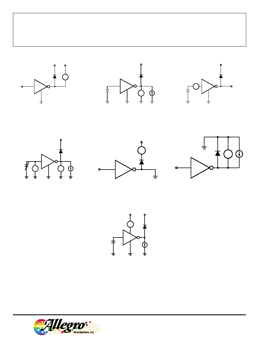
320 W per channel. Both integrated circuits include transient-suppres-
sion diodes that enable use with inductive loads. The input logic is
compatible with most TTL, DTL, LSTTL, and 5 V CMOS logic.
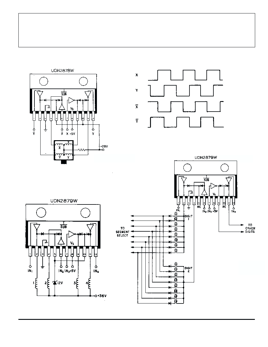
Type UDN2878W and UDN2879W 4 A arrays are identical except
for output-voltage ratings. The former is rated for operation to 50 V
(35 V sustaining), while the latter has a minimum output breakdown
rating of 80 V (50 V sustaining). The lower-cost UDN2879W-2 is
recommended for applications requiring load currents of 3 A or less.
These less expensive devices are identical to the basic parts except for
the maximum allowable load-current rating.
For maximum power-handling capability, all drivers are supplied
in a 12-pin single in-line power-tab package. The tab needs no insula-
tion. External heat sinks are usually required for proper operation of
these devices.
FEATURES
I Output Currents to 4 A
I Output Voltages to 80 V
I Loads to 1280 W
I TTL, DTL, or CMOS Compatible Inputs
I Internal Clamp Diodes
I Plastic Single In-Line Package
I Heat-Sink Tab
QUAD HIGH-CURRENT
DARLINGTON SWITCHES
Always order by complete part number:
Part Number
Max. I
C
Max. V
CEX
Min. V
CE (sus)
UDN2878W
5.0 A
50 V
35 V
UDN2879W
5.0 A
80 V
50 V
UDN2879W-2
4.0 A
80 V
50 V
Data Sheet
29305.10B
2878
AND
2879
ABSOLUTE MAXIMUM RATINGS
at +25
∞
C Free-Air Temperature
for any driver
(unless otherwise noted)
Output Voltage, V
CEX
(UDN2878W) . . . . . . . . . . . . . . . . 50 V
(UDN2879W & UDN2879W-2) . . 80 V
Output Current, l
C
(UDN2878W & UDN2879W) . . . 5.0 A
(UDN2879W-2) . . . . . . . . . . . . . 4.0 A
Input Voltage, V
IN
. . . . . . . . . . . . . . . . 15 V
Input Current, I
IN
. . . . . . . . . . . . . . . 25 mA
Supply Voltage, V
S
. . . . . . . . . . . . . . . 10 V
Total Package Power Dissipation,
P
D
. . . . . . . . . . . . . . . . . . . . See Graph
Operating Ambient Temperature Range,
T
A
. . . . . . . . . . . . . . . . -20
∞
C to +85
∞
C
Storage Temperature Range,
T
S
. . . . . . . . . . . . . . . -55
∞
C to +150
∞
C
Dwg. No. A-11,974
2878
AND
2879
QUAD HIGH-CURRENT
DARLINGTON SWITCHES
115 Northeast Cutoff, Box 15036
Worcester, Massachusetts 01615-0036 (508) 853-5000
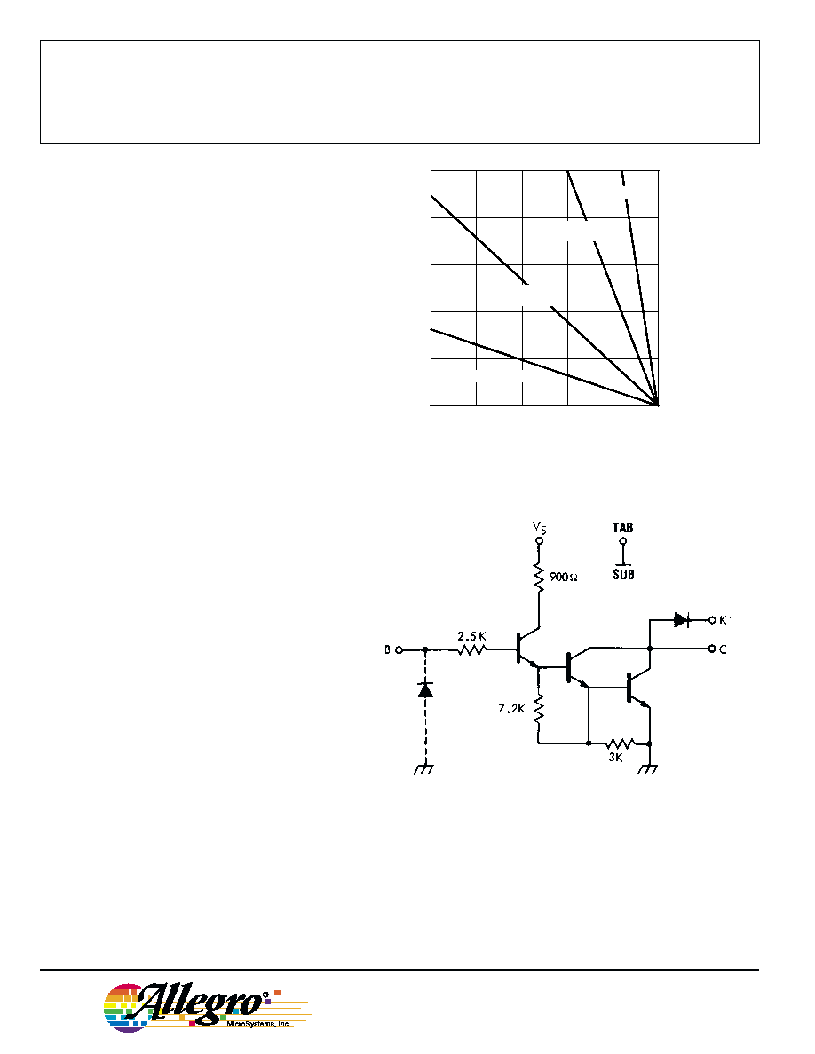
PARTIAL SCHEMATIC
One of 4 Drivers
50
75
100
125
150
10
6
4
2
0
ALLOWABLE PACKAGE POWER DISSIPATION IN WATTS
TEMPERATURE IN
∞C
8
25
R = 2.0
∞C/W
JT
Dwg. GP-012B
FREE AIR, R = 38
∞C/W
JA
3.0
∞C/W HEAT SINK
R = 5.0
∞C/W
JA
12
∞C/W HEAT SINK
R = 14
∞C/W
JA
Dwg. No. A-12,037
NOTE: Pin 3 must be connected to ground for proper operation.
Copyright © 1983, 2000 Allegro MicroSystems, Inc.