 | –≠–ª–µ–∫—Ç—Ä–æ–Ω–Ω—ã–π –∫–æ–º–ø–æ–Ω–µ–Ω—Ç: 3056 | –°–∫–∞—á–∞—Ç—å:  PDF PDF  ZIP ZIP |
Switching Hysteresis
15-90 G
150-250 G
Operating Temp. Range
Device Type Number
-40
∞
C to +85
∞
C
A3046EU
A3058EU
A3056EU
-40
∞
C to +150
∞
C
A3046LU
A3058LU
A3056LU
HALL EFFECT GEAR-TOOTH SENSORS
≠ZERO SPEED
The A3046EU/LU, A3056EU/LU, and A3058EU/LU Hall effect
gear-tooth sensors are monolithic integrated circuits that switch in
response to differential magnetic fields created by ferrous targets.
These devices are ideal for use in gear-tooth-based speed, position,
and timing applications and operate down to zero rpm over a wide
range of air gaps and temperatures. When combined with a back-
biasing magnet and proper assembly techniques, devices can be
configured to give 50% duty cycle or to switch on either leading,
trailing, or both edges of a passing gear tooth or slot.
The six devices differ only in their magnetic switching values and
operating temperature ranges. The low hysteresis of the A3046/56EU
and A3046/56LU makes them perfectly suited for ABS (anti-lock brake
system) or speed sensing applications where maintaining large air
gaps is important. The A3046EU/LU features improved switch point
stability with temperature over the A3056EU/LU. The high hysteresis
of the A3058EU and A3058LU, with their excellent temperature
stability, makes them especially suited to ignition timing applications
where switch-point accuracy (and latching requirements) is extremely
important.
Continued next page...
BENEFITS
s
Senses Ferrous Targets Down to Zero RPM
s
Large Effective Air Gap
s
Wide Operating Temperature Range
s
Operation from Unregulated Supply
s
High-Speed Operation
s
Output Compatible With All Logic Families
s
Reverse Battery Protection
s
Solid-State Reliability
s
Resistant to Physical Stress
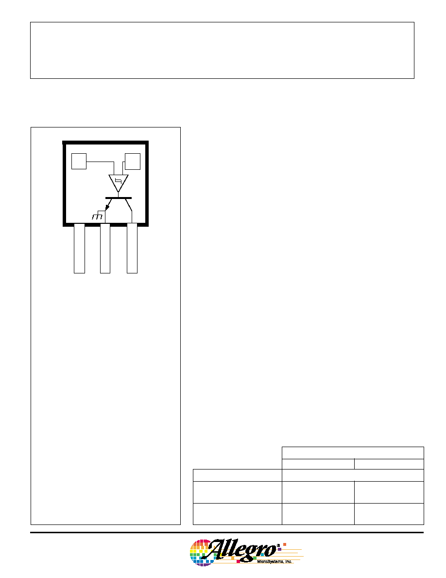
Dwg. PH-012
1
SUPPLY
V
CC
GROUND
3
2
OUTPUT
X
X
Pinning is shown viewed from branded side.
Data Sheet
27612A
ABSOLUTE MAXIMUM RATINGS
Supply Voltage, V
CC
. . . . . . . . . . . . . . 28 V
Reverse Battery Voltage,
V
RCC
. . . . . . . . . . . . . . . . . . . . . . -30 V
Magnetic Flux Density, B . . . . . Unlimited
Output OFF Voltage, V
OUT
. . . . . . . . . 28 V
Reverse Output Voltage, V
OUT
. . . . . -0.5 V
Output Current, I
OUT
. . . . . . . . . . . . 25 mA
Package Power Dissipation, P
D
. . 500 mW
Operating Temperature Range, T
A
Suffix "EU" . . . . . . . . . -40
∞
C to +85
∞
C
Suffix "LU" . . . . . . . . -40
∞
C to +150
∞
C
Storage Temperature Range,
T
S
. . . . . . . . . . . . . . . -65
∞
C to +170
∞
C
3046, 3056,
AND
3058
The A3046xU is not for new design.

3046, 3056,
AND
3058
HALL EFFECT
GEAR-TOOTH SENSORS
≠ZERO SPEED
115 Northeast Cutoff, Box 15036
Worcester, Massachusetts 01615-0036 (508) 853-5000
All devices, when used with a back-
biasing magnet, can be configured to turn ON
or OFF with the leading or trailing edge of a
gear tooth or slot. Changes in fields on the
magnet face caused by a moving ferrous
mass are sensed by two integrated Hall
transducers and are differentially amplified by
on-chip electronics. The on-chip temperature
compensation and Schmitt trigger circuitry
minimizes shifts in effective working air gaps
and switch points over temperature making
these devices ideal for use in ignition timing,
anti-lock braking systems, and speed mea-
surement systems in hostile automotive and
industrial environments.
Each Hall effect digital Integrated circuit
includes two quadratic Hall effect sensing
elements, a voltage regulator, temperature
compensating circuitry, low-level amplifier,
Schmitt trigger, and an open-collector output
driver. The on-board regulator permits
operation with supply voltages of 4.5 to 24
volts. The output stage can switch up to 20
mA at conservatively specified repetition
rates to 20 kHz and is compatible with bipolar
and MOS logic circuits.
FUNCTIONAL BLOCK DIAGRAM
Both magnetic characteristics are available in a choice of two operat-
ing temperature ranges. Suffix EU devices have an operating range of
-40
∞
C to +85
∞
C while suffix LU devices feature an operating range of
-40
∞
C to +150
∞
C. All devices are packaged in a 3-pin plastic SIP.
ELECTRICAL CHARACTERISTICS at V
CC
= 8 V, over operating temperature range.
Limits
Characteristic
Symbol
Test Conditions
Min.
Typ.
Max.
Units
Supply Voltage
V
CC
Operating
4.5
--
24
V
Power-Up State
--
3058* only,
Output is OFF
--
V
CC
= 0 4.5 V, B < B
OP
Output Saturation Voltage
V
OUT(SAT)
I
OUT
= 20 mA, B > B
OP
--
135
400
mV
Output Leakage Current
I
OFF
V
CC
= V
OUT
= 24 V, B < B
RP
--
--
5.0
µ
A
Supply Current
I
CC
V
CC
= 24 V, B < B
RP
--
7.2
14
mA
Output Rise time
t
r
R
L
= 820
, C
L
= 20 pF
--
100
--
ns
Output Fall time
t
f
R
L
= 820
, C
L
= 20 pF
--
100
--
ns
OUTPUT
X
X
Dwg. FH-010
SUPPLY
GROUND
REG
+
≠
1
2
3
Copyright © 1989, 1995 Allegro MicroSystems, Inc.

3046, 3056,
AND
3058
HALL EFFECT
GEAR-TOOTH SENSORS
≠ZERO SPEED
www.allegromicro.com
Part Numbers*
3046
3056
3058
Characteristic
Test Conditions
Min. Typ. Max.
Min. Typ. Max.
Min. Typ. Max.
Operate Point, B
OP
Output Switches OFF to ON,
--
--
150
--
--
150
--
--
250
Release Point, B
RP
Output Switches ON to OFF,
-150
--
--
-150
--
--
-250
--
--
Hysteresis, B
hys
B
OP
-B
RP
, T
A
= +25
∞
C
15
50
90
15
50
90
150
200
250
Change in Trip Point,
--
--
±
50
--
--
±
75
--
--
±
50
B
OP
or
B
RP
MAGNETIC CHARACTERISTICS in gauss at V
CC
= 8 V.
T
A
= +25
∞
C
T
A
= +25
∞
C
NOTES: 1. Magnetic switch points are specified as the
difference in magnetic fields at the two Hall
elements.
2. As used here, negative flux densities are
defined as less than zero (algebraic conven-
tion).
3. Typical values are at T
A
= +25
∞
C.
* Complete part number includes the prefix
`A' and a suffix to identify operating tempera-
ture range and package style. See selection
guide.
Over operating temperature range,
Ref. B
OP
or B
RP
at T
A
= +25
∞
C
TYPICAL OPERATING CHARACTERISTICS
0
5
SUPPLY CURRENT IN mA
SUPPLY VOLTAGE IN VOLTS
Dwg. GH-031
10
9
8
7
6
5
10
15
20
25
T = +25
∞
C
A
B > B
OP
B < B
RP
-50
100
SATURATION VOLTAGE IN mV
AMBIENT TEMPERATURE IN
∞
C
Dwg. GH-033
180
160
140
120
0
50
100
150
200
V = 8 V
I = 20 mA
CC
OUT
-50
5
SUPPLY CURRENT IN mA
AMBIENT TEMPERATURE IN
∞
C
Dwg. GH-032
11
9
8
7
6
0
50
100
150
V = 24 V
CC
10
B > B
OP
B < B
RP

3046, 3056,
AND
3058
HALL EFFECT
GEAR-TOOTH SENSORS
≠ZERO SPEED
115 Northeast Cutoff, Box 15036
Worcester, Massachusetts 01615-0036 (508) 853-5000
24 V
MAX
0
+B
0
OUTPUT VOLTAGE IN VOLTS
DIFFERENTIAL FLUX DENSITY, B
E1
≠ B
E2
Dwg. GH-034
-B
OP
RP
B
B
V
OUT(SAT)
APPLICATIONS INFORMATION
A gear-tooth sensing system consists of the sensor IC, a back-
biasing magnet, an optional pole piece, and a target (Figure 1). The
system requirements are usually specified in terms of the effective
working air gap between the package and the target (gear teeth), the
number of switching events per rotation of the target, temperature and
speed ranges, minimum pulse duration or duty cycle, and switch point
accuracy. Careful choice of the sensor IC, magnet material and
shape, target material and shape, and assembly techniques enables
large working air gaps and high switch-point accuracy over the system
operating temperature range.
Naming Conventions. With a south pole in front of the branded
surface of the sensor, a north pole behind the sensor, the field at the
sensor is defined as positive. As used here, negative flux densities are
defined as less than zero (algebraic convention), e.g., -100 G is less
than -50 G.
Magnet Biasing. In order to sense moving non-magnetized
ferrous targets, these devices must be back-biased by mounting the
unbranded side on a small permanent magnet. Either magnetic pole
(north or south) can be used.
The devices can also be used without a back-biasing magnet.
In this configuration, the sensor can be used to detect a rotating ring
magnet such as those found in brushless dc motors or in speed
sensing applications. Here, the sensor detects the magnetic field
gradient created by the magnetic poles.
Figure 2
TYPICAL TRANSFER CHARACTERISTIC
Figure 1
TYPICAL GEAR-TOOTH SENSING
APPLICATION
BACK-BIASING
MAGNET
OPTIONAL POLE PIECE
SENSOR IC
N
S
TARGET
GEAR
A
Dwg. AH-003
S

3046, 3056,
AND
3058
HALL EFFECT
GEAR-TOOTH SENSORS
≠ZERO SPEED
www.allegromicro.com
Sensor Operation. The A3046EU/LU,
A3056EU/LU, and A3058EU/LU sensor ICs
each contain two integrated Hall transducers
(E1 and E2) that are used to sense a mag-
netic field differential across the face of the
IC (see S
ENSOR
L
OCATION
drawing). Referring
to Figure 2, the trigger switches the output
ON (output LOW) when B
E1
≠ B
E2
> B
OP
and
switches the output OFF (output HIGH) when
B
E1
≠ B
E2
< B
RP
. The difference between B
OP
and B
RP
is the hysteresis of the device.
Figure 3 relates the output state of a
back-biased sensor IC, with switching
characteristics shown in Figure 2, to the
target gear profile and position. Assume a
north pole back-bias configuration (equivalent
to south pole at the face of the device). The
motion of the gear produces a phase-shifted
field at E1 and E2 (Figure 3 (a)); internal
conditioning circuitry subtracts the field at the
two elements (Figure 3 (b)); and the Schmitt
trigger at the output of the conditioning
circuitry switches at the pre-determined
thresholds (B
OP
and B
RP
). As shown (Figure
3 (c)), the IC output is LOW whenever sensor
E1 sees a (ferrous) gear tooth and sensor E2
faces air. The output is HIGH when sensor
E1 sees air and sensor E2 sees the ferrous
target.
A gear-tooth sensor can be configured
(see A
SSEMBLY
T
ECHNIQUES
) to operate as a
latch, a (positive) switch, or a negative
switch. Note the change in duty cycle in
each of the cases (Figure 4).
A latch is a device where the operate
point is greater than zero gauss and the
release point is less than zero gauss. With
the configuration shown in Figure 3, such a
device will switch ON on the leading edge
and OFF on the trailing edge of the target
tooth.
A (positive) switch is a device where
both the operate and release points are
greater than zero gauss (positive values).
Figure 3
GEAR-TOOTH SENSOR OPERATION
OP
B = +25 G
B ≠ B
E1 E2
GEAR
4300 G
4130 G
150 G
0 G
-150 G
RP
B = ≠25 G
V
OUT(SAT)
V
OUT
B & B
E1 E2
OUTPUT DUTY CYCLE
50%
Dwg. WH-003
DIRECTION
OF ROTATION
LEADING
EDGE
TRAILING
EDGE
NORTH
SOUTH
E2
E1
(a)
(b)
(c)
In the configuration shown in Figure 3, such a device will switch ON
and then switch OFF on the leading or rising edge of the target tooth
(Figure 4 (a)).
A negative switch is a device where both the operate and release
points are less than zero gauss (negative values). In the configuration
shown in Figure 3, such a device will switch OFF and then switch ON
on the trailing or falling edge of the target tooth (Figure 4 (b)).
Speed sensors can use any of the three sensor configurations
described. Timing sensors, however, must use a latch to guarantee
dual-edge detection. Latches are most easily made using the
A3058EU or A3058LU device types.