 | –≠–ª–µ–∫—Ç—Ä–æ–Ω–Ω—ã–π –∫–æ–º–ø–æ–Ω–µ–Ω—Ç: 3064 | –°–∫–∞—á–∞—Ç—å:  PDF PDF  ZIP ZIP |

The A3064LKA ac-coupled Hall-effect gear-tooth sensor is a
monolithic integrated circuit that switches in response to changing
differential magnetic fields created by moving ferrous targets. This
device is ideal for use in non-zero-speed, gear-tooth-based speed,
position, and timing applications such as in anti-lock braking systems,
transmissions, and crankshafts.
When coupled with a back-biasing magnet, the sensor can be
configured to turn on or off with the leading or trailing edge of a gear-
tooth or slot. Changes in fields on the magnet face caused by a moving
ferrous mass are sensed by two integrated Hall transducers and are
differentially amplified by on-chip electronics. This differential
sensing design provides immunity to radial vibration within the
device's operating air gap. Steady-state magnet and system offsets are
eliminated using an on-chip differential band-pass filter. This filter
also provides relative immunity to interference from RF and electro-
magnetic sources. The on-chip temperature compensation and Schmitt
trigger circuitry minimizes shifts in effective working air gaps and
switch points over temperature, allowing operation to low frequencies
over a wide range of air gaps and temperatures.
Each Hall-effect digital Integrated circuit includes a voltage
regulator, two quadratic Hall-effect sensing elements, temperature
compensating circuitry, a low-level amplifier, band-pass filter, Schmitt
trigger, and an open-collector output driver. The on-board regulator
permits operation with supply voltages of 4.5 to 24 volts. The output
stage can easily switch 20 mA over the full frequency response range
of the sensor and is compatible with bipolar and MOS logic circuits.
The device is packaged in a 5-pin plastic SIP.
FEATURES
s
Senses Motion of Ferrous Targets
s
Wide Operating Temperature Range
s
Operation to 30 kHz
s
Resistant to EMI
s
Large Effective Air Gap
s
4.5 V to 24 V Operation
s
Output Compatible With All Logic Families
s
Reverse Battery Protection
s
Resistant to Physical Stress
HALL-EFFECT GEAR-TOOTH SENSOR
--AC COUPLED
Always order by complete part number, e.g.,
A3064LKA .
Data Sheet
27612.21
ABSOLUTE MAXIMUM RATINGS
at T
A
= +25
∞
C
Supply Voltage, V
CC
............................. 24 V
Reverse Battery Voltage, V
RCC
.......... -30 V
Magnetic Flux Density, B ............ Unlimited
Output Off Voltage, V
OUT
...................... 24 V
Output Current, I
OUT
......................... 25 mA
Package Power Dissipation,
P
D
............................................ 500 mW
Operating Temperature Range,
T
A
............................... -40
∞
C to +150
∞
C
Storage Temperature Range,
T
S
............................... -65
∞
C to +170
∞
C
V
CC
1
4
3
2
5
X
X
Dwg. PH-011-1
SUPPLY
OUTPUT
GROUND
FILTER
FILTER
Pinning is shown viewed from branded side.
3064

3064
HALL-EFFECT
GEAR-TOOTH SENSOR
--AC COUPLED
115 Northeast Cutoff, Box 15036
Worcester, Massachusetts 01615-0036 (508) 853-5000
2
MAGNETIC CHARACTERISTICS over operating temperature and supply voltage range.
Limits
Characteristic
Symbol
Test Conditions
Min.
Typ.
Max.
Units
Operate Point
B
OP
Output switches on to off
0
15
27.5
G
Release Point
B
RP
Output switches off to on
-12.5
0
7.5
G
Hysteresis
B
hys
B
OP
- B
RP
5.0
15
35
G
FUNCTIONAL BLOCK DIAGRAM
ELECTRICAL CHARACTERISTICS over operating temperature and supply voltage range.
Limits
Characteristic
Symbol
Test Conditions
Min.
Typ.
Max.
Units
Supply Voltage
V
CC
Operating
4.5
--
24
V
Output Saturation Voltage
V
OUT(SAT)
I
OUT
= 18 mA, B < B
RP
--
141
400
mV
Output Leakage Current
I
OFF
V
OUT
= 24 V, B > B
OP
--
--
5.0
µ
A
Supply Current
I
CC
B < B
RP
--
11
20
mA
B > B
OP
--
9.6
--
mA
High-Frequency Cutoff
f
coh
-3 dB
30
--
--
kHz
Output Rise time
t
r
V
OUT
= 12 V, R
L
= 820
--
0.04
0.2
µ
s
Output Fall time
t
f
V
OUT
= 12 V, R
L
= 820
--
0.18
0.3
µ
s
NOTES: 1. Magnetic switch points are specified as the difference in magnetic fields at the two Hall elements.
2. As used here, negative flux densities are defined as less than zero (algebraic convention).
3. Typical values are at T
A
= 25
∞
C and V
CC
= 12 V.
4. 1 gauss (G) is exactly equal to 0.1 millitesla (mT).
OUTPUT
X
X
Dwg. FH-008-1
SUPPLY
GROUND
FILTER
FILTER
REG
+
-
1
4
5
2
3
Copyright © 2001 Allegro MicroSystems, Inc.

3064
HALL-EFFECT
GEAR-TOOTH SENSOR
--AC COUPLED
www.allegromicro.com
3
TYPICAL OPERATING CHARACTERISTICS
SWITCH POINTS
OUTPUT SATURATION VOLTAGE
OPERATE POINT
0
50
100
AMBIENT TEMPERATURE IN
∞
C
-50
Dwg. GH-056-1
DIFFERENTIAL FLUX DENSITY IN GAUSS
20
30
10
0
RELEASE POINT
V = 12 V
CC
150
-10
-25
25
75
125
200
50
150
100
Dwg. GH-055-2
SATURATION VOLTAGE IN mV
0
SUPPLY VOLTAGE IN VOLTS
5
10
15
20
25
I = 18 mA
T = +25
∞
C
OUT
A
0
25
50
75
100
300
0
AMBIENT TEMPERATURE IN
∞
C
200
100
-50
Dwg. GH-029-6
SATURATION VOLTAGE IN mV
150
-25
125
I = 18 mA
V = 12 V
OUT
CC

3064
HALL-EFFECT
GEAR-TOOTH SENSOR
--AC COUPLED
115 Northeast Cutoff, Box 15036
Worcester, Massachusetts 01615-0036 (508) 853-5000
4
TYPICAL OPERATING CHARACTERISTICS
SUPPLY CURRENT
The A3064LKA is a versatile high-precision differential
sensing device that can be used in a wide range of applications.
Careful choice of the sensor IC, target material and shape,
magnet material and shape, and assembly techniques enables
large working air gaps and high switch-point accuracy over the
system operating temperature range.
Magnet Biasing. To sense moving non-magnetized
ferrous targets, these devices must be back biased by mounting
the unbranded side on a small permanent magnet. Either
magnetic pole (north or south) can be used.
The devices can be used without a back-biasing magnet.
For example, the sensor can be used to detect a rotating ring
magnet such as those found in brushless dc motors or in speed
sensing applications.
Sensor Operation. These sensor ICs each contain two
integrated Hall transducers (E1 and E2) that are used to sense a
magnetic field differential across the face of the IC (see Sensor
Location drawing). Referring to the Typical Transfer Charac-
teristic (Figure 1), the trigger switches the output off (output
high) when B
E1
- B
E2
>
B
OP
and switches the output on (output
APPLICATIONS INFORMATION
0
SUPPLY CURRENT IN mA
20
15
10
5
0
25
50
75
100
AMBIENT TEMPERATURE IN
∞
C
-50
Dwg. GH-028-9
125
-25
V = 24 V
CC
150
B < B
RP
B > B
OP
+B
0
OUTPUT VOLTAGE
FLUX DENSITY
Dwg. GH-007-6
0
CC
V
V
OUT(SAT)
OP
B
RP
B
+V
-B
Figure 1
TYPICAL TRANSFER CHARACTERISTIC
0
SUPPLY CURRENT IN mA
SUPPLY VOLTAGE IN VOLTS
Dwg. GH-031-3
10
5
10
15
20
25
T = +25
∞
C
A
B < B
RP
B > B
OP
0
SUPPLY CURRENT IN mA
20
15
5
3064
HALL-EFFECT
GEAR-TOOTH SENSOR
--AC COUPLED
www.allegromicro.com
5
Figure 2
OP
B = +15 G
B ≠ B
E1 E2
GEAR
4300 G
4150 G
150 G
0 G
-150 G
RP
B = 0 G
V
OUT(SAT)
V
OUT
B & B
E1 E2
OUTPUT DUTY CYCLE
50%
Dwg. WH-003-3
DIRECTION
OF ROTATION
LEADING
EDGE
TRAILING
EDGE
NORTH
SOUTH
E2
E1
(a)
(b)
(c)
low) when B
E1
- B
E2
< B
RP
. The difference between B
OP
and
B
RP
is the hysteresis of the device.
Note that powering up in the absence of a differential
magnetic field (less than the device B
OP
and higher than the
device B
RP
) will allow an indeterminate output state. The
correct output state is warranted after the first excursion beyond
B
OP
or B
RP
.
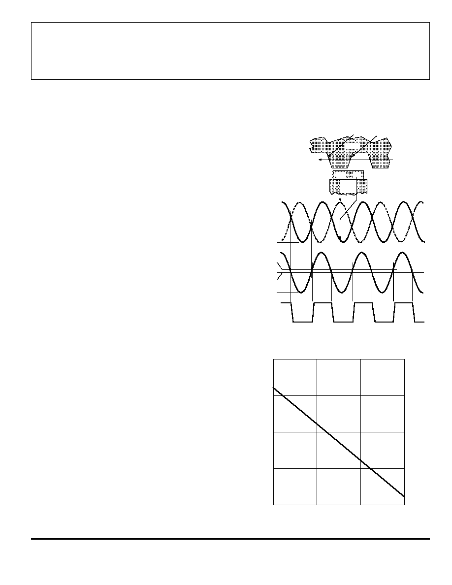
Figure 2 relates the output state of a back-biased sensor IC,
with switching characteristics shown in Figure 1, to the target
gear profile and position. Assume a north pole back-bias
configuration (equivalent to a south pole at the face of the
device). The motion of the gear produces a phase-shifted field
at E1 and E2 (Figure 2(a)); internal conditioning circuitry
subtracts the fields at the two elements (Figure 2(b)); this
differential field is band-pass filtered to remove dc offset
components and then fed into a Schmitt trigger; the Schmitt
trigger switches the output transistor at the thresholds B
OP
and
B
RP
. As shown (Figure 2(c)), the IC output is low whenever
sensor E2 faces a (ferrous) gear tooth and sensor E1 faces air.
The output is high when sensor E1 faces air and sensor E2 faces
a ferrous target.
AC-Coupled Operation. Steady-state magnet and
system offsets are eliminated using an on-chip differential band-
pass filter. The lower frequency cut-off of this patented filter is
set using an external capacitor, the value of which can range
from 0.01
µ
F to 10
µ
F. The high-frequency cut-off of this filter
is set at 30 kHz by an internal integrated capacitor.
The differential structure of this filter improves the ability
of the IC to reject single-ended noise on the ground or supply
line and, as a result, makes it more resistant to radio-frequency
and electromagnetic interference typically seen in hostile
remote-sensing environments. This filter configuration also
increases system tolerance to capacitor degradation at high
temperatures, allowing the use of an inexpensive external
ceramic capacitor.
Low-Frequency Operation. Low-frequency operation
of the sensor is set by the value of an external capacitor.
Ideally, the differential flux density range (determined by the
applied target) vs. air gap assumes a perfect sinusoidal input.
Figure 3 provides the low-frequency cut-off (-3 dB point) of the
filter as a function of capacitance value. This information
should be used with care. In reality, when used with gear teeth,
Figure 3
0.1
1.0
10
1.0
10
CAPACITANCE IN
µ
F
100
0.1
0.01
Dwg. GH-025
LOW-FREQUENCY CUTOFF IN Hz
1 k
APPLICATIONS INFORMATION (cont'd)