
This Hall-effect switch is a monolithic integrated circuit designed to
operate continuously over extended temperatures to +85
∞C. The unipo-
lar switching characteristic makes this device ideal for use with a simple
bar or rod magnet. The A3161ELT and A3161EUA are identical except
for package.
Each device includes a voltage regulator for operation with supply
voltages of 3.5 to 25 volts, reverse battery protection diode, quadratic
Hall-voltage generator, temperature compensation circuitry, small-signal
amplifier, Schmitt trigger, and a constant-current open-collector output.
Noise radiation is limited by control of the output current slew rate.
Two package styles provide a magnetically optimized package for
most applications. Suffix `LT' is a miniature SOT-89/TO-243AA
transistor package for surface-mount applications; suffix `UA' is a three-
lead ultra-mini SIP for through-hole mounting.
HALL-EFFECT SWITCH
FOR 2-WIRE APPLICATIONS
Always order by complete part number, e.g., A3161ELT .
Data Sheet
27621.30A
Pinning is shown viewed from branded side.
ABSOLUTE MAXIMUM RATINGS
at T
A
= +25
∞
C
FEATURES and BENEFITS
I
Internal Current Regulator for 2-Wire Operation
I
Output Slew Rate Controlled
I
3.5 V to 25 V Operation ... Needs Only An Unregulated Supply
I
Reverse Battery Protection
I
Excellent Temp. Stability
I
Activate with Small, Commercially Available Permanent Magnets
I
Small Size
I
Solid-State Reliability ... No Moving Parts
I
Resistant to Physical Stress
3161
Supply Voltage, V
CC
Continuous ................................. 28 V
Surge (t
w
100 ms) .................... 40 V
Reverse Battery Voltage, V
RCC
Continuous ................................ -25 V
Surge (t
w
100 ms) ................... -40 V
Magnetic Flux Density, B ....... Unlimited
Output OFF Voltage, V
OUT
.............. 28 V
Operating Temperature Range,
T
A
............................. -40
∞
C to +85
∞
C
Storage Temperature Range,
T
S
........................... -65
∞
C to +170
∞
C
Dwg. PH-003-3
1
SUPPLY
V
CC
GROUND
3
2
OUTPUT
X
3161
HALL-EFFECT SWITCH
FOR 2-WIRE APPLICATIONS
115 Northeast Cutoff, Box 15036
Worcester, Massachusetts 01615-0036 (508) 853-5000
Limits
At T
A
= +25
∞
C
Over Oper. Temp. Range
Characteristic
Symbol
Min.
Typ.
Max.
Min.
Typ.
Max.
Units
Operate Point (output turns OFF)
B
OP
≠
130
160
≠
130
160
G
Release Point (output turns ON)
B
RP
30
110
≠
30
110
≠
G
Hysteresis (B
OP
- B
RP
)
B
hys
5.0
20
≠
5.0
20
80
G
Limits
Characteristic
Symbol
Test Conditions
Min.
Typ.
Max.
Units
Supply Voltage
V
CC
Operating
3.5
--
25
V
Load Current
I
OUT
+ I
CC
3.5 V
V
OUT
< 12 V, B < B
RP
12
15
17
mA
(2-wire application)
V
OUT
12 V, B < B
RP
12
15
19
mA
B > B
OP
--
3.5
5.0
mA
Output Current
I
OUT
B < B
RP
--
12
--
mA
I
OFF
V
OUT
= 24 V, B > B
OP
--
<1.0
10
µA
Output Saturation Voltage
V
OUT
I
OUT
= 5 mA, B < B
RP
≠
0.9
1.5
V
Output Slew Rate
di/dt
C
L
= 20 pF
--
7.0
20
mA/
µs
Output Settling Time
t
sd
C
L
= 20 pF
--
--
20
µs
ELECTRICAL CHARACTERISTICS over operating voltage and temperature ranges.
Copyright © 1998, 1999, Allegro MicroSystems, Inc.
MAGNETIC CHARACTERISTICS over operating supply voltage range.
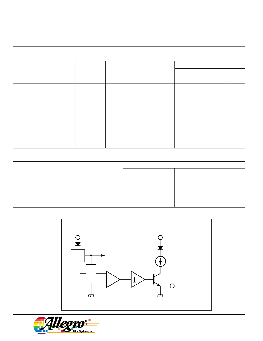
FUNCTIONAL BLOCK DIAGRAM
NOTE:Typical values are at T
A
= +25
∞C and V
CC
= 12 V.
V
CC
X
REG.
Dwg. FH-017
GROUND
OUTPUT
3
2
1

3161
HALL-EFFECT SWITCH
FOR 2-WIRE APPLICATIONS
115 Northeast Cutoff, Box 15036
Worcester, Massachusetts 01615-0036 (508) 853-5000
Suffix "LT"
SENSOR LOCATIONS
OPERATION
The output of these devices (pin 3) switches OFF when the magnetic
field at the Hall sensor exceeds the operate point threshold (B
OP
). When the
magnetic field is reduced to below the release point threshold (B
RP
), the
device output switches ON. The difference in the magnetic operate and
release points is called the hysteresis (B
hys
) of the device. This built-in
hysteresis allows clean switching of the output even in the presence of
external mechanical vibration and electrical noise.
Suffix "UA"
APPLICATIONS INFORMATION
These devices are normally operated in a 2-wire mode, where the supply
terminal and the output terminal are tied together. An external comparator
detects the change in total supply current by the addition (output off, B > B
OP
)
or subtraction (output on, B < B
RP
) of I
OUT
.
Hall effect applications information is available in the "Hall-Effect IC
Applications Guide", which can be found in the latest issue of the Allegro
MicroSystems Electronic Data Book, AMS-702 or Application Note 27701,
or at
www.allegromicro.com
.
TYPICAL 2-WIRE APPLICATION
0.045"
1.14 mm
1
3
2
Dwg. MH-008-7
0.030"
0.76 mm
NOM
ACTIVE AREA DEPTH
0.085"
2.16 mm
A
1
3
2
Dwg. MH-011-8
0.018"
0.46 mm
NOM
BRANDED
SURFACE
ACTIVE AREA DEPTH
0.078"
1.98 mm
0.054"
1.36 mm
A
0.85 V
1
V
CC
3
2
X
100
Dwg. EH-011A
0.1
µF
SUPPLY
Icc + Io
UT
≠
+
100
125
150
175
200
3.0
0
OUTPUT CURRENT in mA
MAGNETIC FLUX DENSITY in GAUSS
12
9.0
6.0
75
Dwg. GH-007-1
50
25
0
15
B
OP
B
RP
T
A
= +25
∞C
Allegro

