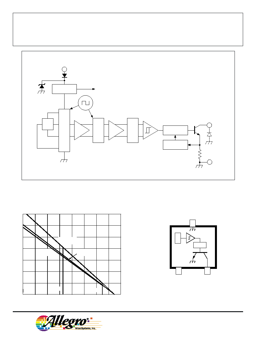
The A3280--, A3281--, and A3283-- Hall-effect latches are ex-
tremely temperature-stable and stress-resistant sensors especially suited
for operation over extended temperature ranges to +150
∞C. Superior
high-temperature performance is made possible through dynamic offset
cancellation, which reduces the residual offset voltage normally caused
by device overmolding, temperature dependencies, and thermal stress.
The three devices are identical except for magnetic switch points.
Each device includes on a single silicon chip a voltage regulator,
Hall-voltage generator, small-signal amplifier, chopper stabilization,
Schmitt trigger, and a short-circuit protected open-collector output to
sink up to 25 mA. A south pole of sufficient strength will turn the
output on. A north pole is necessary to turn the output off. An on-board
regulator permits operation with supply voltages of 4.2 to 24 volts.
The first character of the part number suffix determines the device
operating temperature range; suffix `E≠' is for -40
∞C to +85∞C and
`L≠' is -40
∞C to +150∞C. Three package styles provide a magnetically
optimized package for most applications. Suffix `≠LH' is a miniature
low-profile surface-mount package, `≠LT' is a miniature SOT-89/TO-
243AA transistor package for surface-mount applications; while suffix
`≠UA' is a three-lead ultra-mini-SIP for through-hole mounting.
Data Sheet
27609.20
FEATURES
I Symmetrical Switch Points
I Resistant to Physical Stress
I Superior Temperature Stability
I Output Short-Circuit Protection
I Operation From Unregulated Supply
I Reverse Battery Protection
I Solid-State Reliability
I Small Size
3280, 3281,
AND
3283
Supply Voltage, V
CC
........................ 26.5 V
Reverse Battery Voltage, V
RCC
.......... -30 V
Magnetic Flux Density, B ........... Unlimited
Output Off Voltage, V
OUT
................... 26 V
Continuous Output Current,
I
OUT
....................... Internally Limited
Reverse Output Current, I
OUT
........ -50 mA
Package Power Dissipation, P
D
. See Graph
Junction Temperature, T
J
............... +170
∞
C
Operating Temperature Range, T
A
Suffix `E≠' .................. -40
∞
C to +85
∞
C
Suffix `L≠' ................ -40
∞
C to +150
∞
C
Storage Temperature Range,
T
S
.............................. -65
∞
C to +170
∞
C
ABSOLUTE MAXIMUM RATINGS
at T
A
= +25
∞
C
Pinning is shown viewed from branded side.
Always order by complete part number: the prefix `A' + the basic four-
digit part number + a suffix to indicate operating temperature range +
a suffix to indicate package style, e.g., A3281ELH .
CHOPPER-STABILIZED, PRECISION
HALL-EFFECT LATCHES
Dwg. PH-003-2
1
SUPPLY
V
CC
GROUND
3
2
OUTPUT
X
PTCT
Suffix '≠LT' & '≠UA' Pinning

3280, 3281,
AND
3283
CHOPPER-STABILIZED,
PRECISION
HALL-EFFECT LATCHES
www.allegromicro.com
3
Part Numbers
1
A3280
A3281
A3283
Characteristic
Test Conditions
Min.
Typ.
Max.
Min.
Typ.
Max.
Min.
Typ.
Max.
Units
Operate Point, B
OP
at T
A
= +25
∞C and T
A
= max.
5.0
22
40
15
50
90
100
150
180
G
at T
A
= -40
∞C
5.0
≠
40
15
≠
90
100
≠
200
G
Release Point, B
RP
at T
A
= +25
∞C and T
A
= max.
-40
-23
-5.0
-90
-50
-15
-180
-150
-100
G
at T
A
= -40
∞C
-40
≠
-5.0
-90
≠
-15
-200
≠
-100
G
Hysteresis, B
hys
at T
A
= +25
∞C and T
A
= max.
10
45
80
30
100
180
≠
300
360
G
(B
OP
- B
RP
)
at T
A
= -40
∞C
≠
≠
80
≠
≠
180
≠
≠
400
G
NOTES:1. Complete part number includes a suffix to identify operating temperature range (E or L) and
package type (LH, LT, or UA).
2. As used here, negative flux densities are defined as less than zero (algebraic convention) and -50 G is less than +10 G.
3. Typical Data is at T
A
= +25
∞C and V
CC
= 12 V and is for design information only.
Limits
Characteristic
Symbol
Test Conditions
Min.
Typ.
Max.
Units
Supply Voltage Range
V
CC
Operating, T
J
< 170
∞C
1
4.2
≠
24
V
Output Leakage Current
I
OFF
V
OUT
= 24 V, B < B
RP
≠
≠
10
µA
Output Saturation Voltage
V
OUT(SAT)
I
OUT
= 20 mA, B > B
OP
≠
185
500
mV
Output Current Limit
I
OM
B > B
OP
30
≠
60
mA
Power-On Time
t
po
V
CC
> 4.2 V
≠
≠
50
µs
Chopping Frequency
f
C
≠
340
≠
kHz
Output Rise Time
t
r
R
L
= 820
, C
L
= 20 pF
≠
0.2
2.0
µs
Output Fall Time
t
f
R
L
= 820
, C
L
= 20 pF
≠
0.1
2.0
µs
Supply Current
I
CC
B < B
RP
, V
CC
= 12 V
≠
3.0
8.0
mA
B > B
OP
, V
CC
= 12 V
≠
4.0
8.0
mA
Reverse Battery Current
I
CC
V
RCC
= -30 V
≠
≠
-5.0
mA
Zener Voltage
V
Z
+ V
D
I
CC
= 15 mA, T
A
= 25
∞C
28
32
37
V
Zener Impedance
z
z
+ z
D
I
CC
= 15 mA, T
A
= 25
∞C
≠
50
≠
NOTES:1. Maximum voltage must be adjusted for power dissipation and junction temperature.
2. B
OP
= operate point (output turns on); B
RP
= release point (output turns off).
3. Typical Data is at T
A
= +25
∞C and V
CC
= 12 V and is for design information only.
ELECTRICAL CHARACTERISTICS over operating temperature range.
MAGNETIC CHARACTERISTICS over operating supply voltage range.
3280, 3281,
AND
3283
CHOPPER-STABILIZED,
PRECISION
HALL-EFFECT LATCHES
115 Northeast Cutoff, Box 15036
Worcester, Massachusetts 01615-0036 (508) 853-5000
4
TYPICAL OPERATING CHARACTERISTICS
as a function of temperature
0
50
100
AMBIENT TEMPERATURE IN
∞C
-50
Dwg. GH-026-3
SWITCH POINTS IN GAUSS
0
10
OPERATE POINT
150
-25
25
75
125
20
30
40
50
-50
-40
-30
-20
-10
V
CC
= 4.5 V
V
CC
= 24 V
RELEASE POINT
0
50
100
AMBIENT TEMPERATURE IN
∞C
-50
Dwg. GH-026-4
SWITCH POINTS IN GAUSS
0
20
OPERATE POINT
150
-25
25
75
125
40
60
80
100
-100
-80
-60
-40
-20
V
CC
= 4.5 V to 24 V
RELEASE POINT
* Complete part number includes a suffix denoting operating temperature range (E or L) and package type (LH, LT, or UA).
A3283* SWITCH POINTS
A3280* SWITCH POINTS
A3281* SWITCH POINTS
0
50
100
AMBIENT TEMPERATURE IN
∞C
-50
Dwg. GH-026-6
SWITCH POINTS IN GAUSS
0
40
OPERATE POINT
150
-25
25
75
125
80
120
160
200
-200
-160
-120
-80
-40
V
CC
= 4.5 V
V
CC
= 24 V
RELEASE POINT
3280, 3281,
AND
3283
CHOPPER-STABILIZED,
PRECISION
HALL-EFFECT LATCHES
www.allegromicro.com
5
* Complete part number includes a suffix denoting operating temperature range (E or L) and package type (LH, LT, or UA).
4.0
4.5
5.0
SUPPLY VOLTAGE IN VOLTS
3.0
Dwg. GH-021-1
3.5
RELEASE POINT
SWITCH POINT IN GAUSS
80
40
0
-40
-80
OPERATE POINT
24
T
A
= 150
∞C
T
A
= -40
∞C
4.0
4.5
5.0
SUPPLY VOLTAGE IN VOLTS
3.0
Dwg. GH-021-3
3.5
RELEASE POINT
SWITCH POINT IN GAUSS
40
20
0
-20
-40
OPERATE POINT
24
T
A
= 150
∞C
T
A
= -40
∞C
TYPICAL OPERATING CHARACTERISTICS
as a function of temperature (cont'd)
0
25
50
75
100
300
0
AMBIENT TEMPERATURE IN
∞C
200
100
-50
Dwg. GH-029-4
SATURATION VOLTAGE IN mV
150
-25
125
I
OUT
= 20 mA
V
CC
= 12 V
6.0
SUPPLY CURRENT IN mA
5.0
4.0
3.0
2.0
0
25
50
75
100
AMBIENT TEMPERATURE IN
∞C
-50
Dwg. GH-028-5
125
-25
150
OUTPUT ON, B > B
OP
OUTPUT OFF, B < B
RP
V
CC
= 12 V
SUPPLY CURRENT
OUTPUT SATURATION VOLTAGE
A3280* SWITCH POINTS
A3281* SWITCH POINTS
TYPICAL OPERATING CHARACTERISTICS
as a function of supply voltage