8980
S
UPER
S
ERVO
TM
SPINDLE & VOICE-COIL
ACTUATION MANAGER/DRIVER
DISCONTINUED PRODUCT
-- FOR REFERENCE ONL
Y
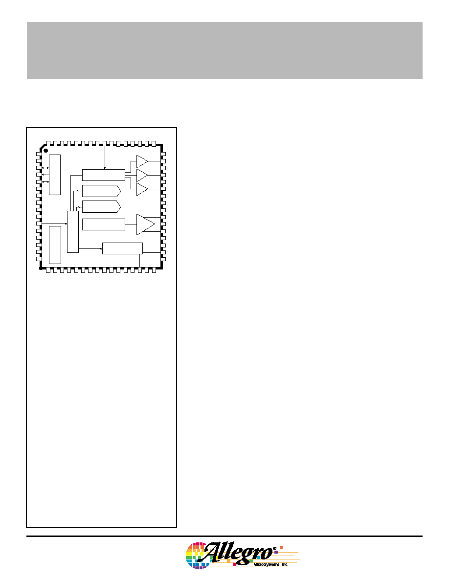
Dwg. PP-048
V
REF
V
REF(X2)
SER DATA IN
C TAP
12
ADJUST
8
VOLTAGE REF.
SERIAL INTERFACE
SPIN-DEMAND
SERVO-DEMAND
BACK-EMF and
COMMUTATION LOGIC
SERVO CONTROL
MULTIPLEXER
ENERGY MANAGER
Dwg. PP-048
S
UPER
S
ERVO
TM
SPINDLE & VOICE-COIL
ACTUATION MANAGER/DRIVER
FEATURES
Voice Coil Motor Driver:
s
Low r
DS(on)
MOS Outputs
s
Lossless Current Sensing
s
Zero Deadband
s
User-Adjustable Transconductance Gain
s
Retract Circuitry Functional to 0 V
The A8980CJT provides complete drive, management, and control
of the voice-coil and spindle motor power actuation subsystems used
in hard disk drives. Extensive programmable control features and
system diagnostics are provided via a serial interface under the
direction of an external microcontroller. The large-scale integration
and use of advanced DABiC
TM
(digital/analog-BiCMOS) merged
technologies results in minimum power dissipation, minimum operating
voltage requirements, and minimum external components.
The spindle drive function incorporates a three-phase MOS power
driver and a back-EMF sensing motor commutation scheme. Internal
logic and analog circuitry provide complete start-up and
�
C-assisted
run modes without the need for snubbers or other external compo-
nents. Additional headroom is achieved by a proprietary circuit, which
eliminates the need for an external current-sense resistor. Intrinsic
ground clamp and flyback diodes are also provided.
The voice-coil function contains a 12-bit DAC, tunable low-pass
and notch filters, and a full-bridge power driver. The MOS outputs
provide increased available voltage and lower power dissipation over
bipolar devices. Voice-coil current is sensed by internal circuitry that
eliminates the need for an external current-sense resistor. Additional
internal circuitry can be configured to provide an over-velocity fault
limit by utilizing the internally monitored current of the voice-coil motor.
The spindle and voice-coil control functions are supplemented by
an E
NERGY
M
ANAGER
TM subsystem, which efficiently channels available
power to protect the heads and the data disk during system failure or
normal system shutdown. Synchronous rectification of spindle
back-EMF voltage provides nearly lossless conversion of spindle
rotational inertia into power to operate the voice coil motor for parking
the heads. A dc-to-dc converter provides continuous operation at
minimum supply voltages. In addition, the E
NERGY
M
ANAGER
subsystem
provides several sleep modes and latched fault states for undervoltage
or thermal faults.
The A8980CJT is supplied in a 64-lead thin quad flatpack for
surface-mount applications.
Output current rating may be restricted to a value
determined by system concerns and factors.
These include: system duty cycle and timing,
ambient temperature, and use of any heatsinking
and/or forced cooling.
ABSOLUTE MAXIMUM RATINGS
at T
A
= +25
�
C
Load Supply Voltage, V
CC(PWR)
.......... 7.0 V
Spindle Output Current, I
OUT(S)
.........
�
1.6 A
Voice-Coil Output Current, I
OUT(S)
....
�
0.9 A
Output Current, I
OUT(S)
......................
�
1.6 A
Logic Supply Voltage V
CC(D)
............... 6.0 V
Operating Temperature Range,
T
A
..................................... 0
�
C to +70
�
C
Data Sheet
26310
8980
8980
S
UPER
S
ERVO
TM
SPINDLE & VOICE-COIL
ACTUATION MANAGER/DRIVER
115 Northeast Cutoff, Box 15036
Worcester, Massachusetts 01615-0036 (508) 853-5000
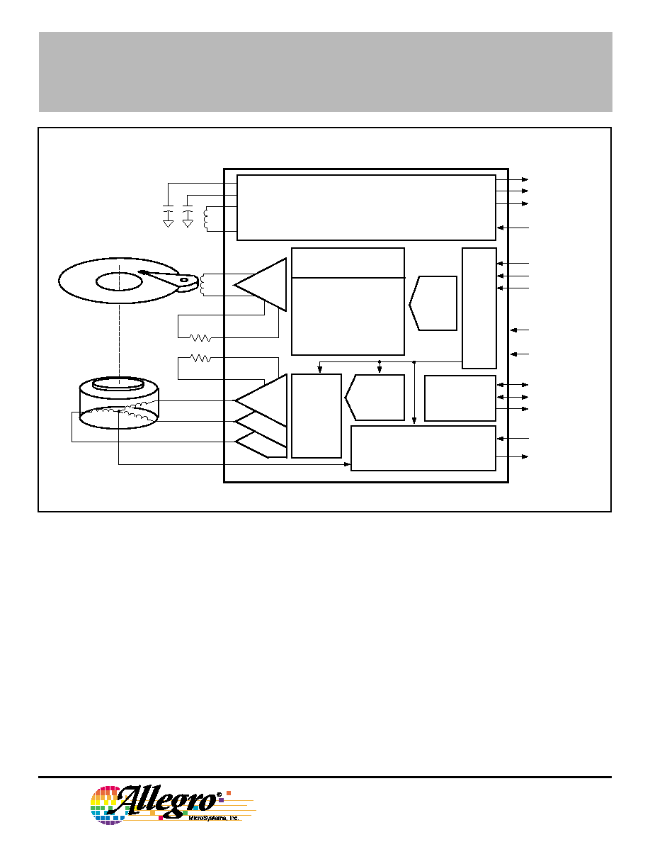
FUNCTIONAL BLOCK DIAGRAM
Dwg. FP-028B
DIGITAL MUX OUT
DATA ENABLE
2 V
REF
V
REF
ANALOG MUX 1
CLOCK
TACH
UV TRIP ADJUST
ANALOG MUX 2
EXTERNAL
COMMUTATION
2 MHz CLOCK
RETRACT
SERIAL DATA IN
BACK-EMF AND
COMMUTATION LOGIC
CONFIGURATION
CONTROL
SERVO CONTROL
�
C SERIAL INTERFACE
SLEW
RATE
CONTROL
POWER-ON
RESET (TO
�
C)
g
m
R
gm
R
gm
ENERGY MANAGER
CONTROLLED RETRACT
DC-DC CONVERSION
SLEEP MODES
UV FAULT
THERMAL SHUTDOWN
TUNABLE
LOW-PASS
FILTER
NOTCH
FREQUENCY,
DEPTH, &
DAMPING
OVER-VELOCITY FAULT
12-BIT
SERVO-
DEMAND
DAC
8-BIT
SPIN-DEMAND
DAC
IN / OUT MUX
g
m
Energy Manager:
s
3.0 V to 5.5 V Operation
s
Independent Power-Down (Sleep) Modes for all
Functional Blocks
s
Efficient Synchronous Rectification Supplies Power
During Blackout
s
Thermal Fault Shutdown Circuitry
s
Trimmed Bandgap Voltage Reference
s
Smart DAC Reference Generator
s
Programmable Voltage Reference for Relative Ground
s
Over-Velocity Fault Circuitry
s
Supply Under-Voltage Monitor with Adjustable
Trip Point
s
System Diagnostics Data Out
s
Power-On Reset Generator
Spindle Motor Controller/Driver:
s
Low r
DS(on)
MOS Outputs
s
Back-EMF Circuitry Eliminates Hall-Effect Sensors
s
Programmable Slew Rate Eliminates Snubbers
s
Lossless Current Sensing
s
Improved Speed Disturbance Performance
s
Dynamic Braking with Delay
s
Active Braking
Servo Compensator/Notch:
s
Over-Velocity Fault Circuitry
s
12-Bit Servo-Demand DAC
s
Programmable Complex Pole Low-pass-Filter
s
Programmable Notch Frequency, Depth, and Damping
Copyright � 1992, 1994, Allegro MicroSystems, Inc.

8980
S
UPER
S
ERVO
TM
SPINDLE & VOICE-COIL
ACTUATION MANAGER/DRIVER
Notch Filter.
This notch filter has a programmable center
frequency and programmable notch depth to provide truly independent
control of notch damping. Enough range and granularity are provided
to allow versatile and accurate out-of-band attenuation of undesirable
energy sources.
Actuator Transconductance Amplifier.
The final trans-
conductance function of the voice-coil actuation signal path is
achieved by monitoring the load current and generating an error
voltage to drive a local g
m
amplifier control loop. The error voltage is
scaled by an external precision resistor (R
gm(act)
). This resistor does
not carry load current and is intended only for accurate determination
of the transconductance. The function is:
g
m(act)
= A/V
and I
OUT
= V
SERVO
� g
m(ACT)
.
Actuator Power Outputs.
The voice-coil output driver is a
full-bridge power driver operating in a class-B mode. The power
output devices are enhancement-mode MOS transistors. Special
internal circuitry results in nearly zero cross-over distortion when
switching from one source/sink pair to another.
FUNCTIONAL DESCRIPTION
ACTUATOR
Servo-Demand DAC.
A 12-bit DAC
is provided to bridge the DSP "soft" domain
to the analog hardware domain. The term
"demand" refers to the distinction between
the newly requested voice-coil current and
the prior current being supplied. The DAC,
operating in straight binary format, spans the
full dynamic range between a large signal
velocity and a precision position mode. The
DAC output is updated synchronously with
the notch functions to avoid the creation of
aliasing products.
Low-Pass Filter.
This double, non-
intrinsic complex-pole low-pass filter is
provided to attenuate undesirable, out-of-
band information. The input of this discrete
time filter is sampled synchronously with the
12-bit DAC and notch function in order to
avoid aliasing products.
VM
V
BOOST(H)
VBOOST(L)
V + V
UNDER-VOLTAGE
FAULT
V
BOOST(H)
VBOOST(L)
SPINDLE
MOTOR DRIVERS
V
BOOST(H)
V
BOOST(L)
VOICE-COIL
DRIVER
TRIP ADJ
POWER
ON
RESET
POR
OUT
REF(x2)
V
REF
V
REFERENCE
ADJUST
V
BOOST(L)
V
BOOST(L)
ADJUST
(FROM SERIAL INTERFACE)
V
V
BOOST(L)
T
J
SHUTDOWN /
SLEEP
DC M
CC(A)
V
CC(A)
V
CC(D)
VCC(PWR)
CC(A)
V
L FLYBACK
CC(A)
V
BG
V
BG
V
BG
V
VDC
OVER -
VELOCITY
FAULT
RETRACT
MODE
V
CC(A)
REF
V +
V
REF
2
VEL
FILTERED
V
REF
V -
V
REF
2
V
CC(D)
VRETRACT
BG
V
ADJUST
(FROM SERIAL
INTERFACE)
x2
�
2
BANDGAP
VOLTAGE
REFERENCE
DC-TO-DC
CONVERTER
THERMAL
FAULT
RETRACT
VOLTAGE
REFERENCE
R
gm(act)
5800

8980
S
UPER
S
ERVO
TM
SPINDLE & VOICE-COIL
ACTUATION MANAGER/DRIVER
115 Northeast Cutoff, Box 15036
Worcester, Massachusetts 01615-0036 (508) 853-5000
SPINDLE
The spindle function is a three-phase
back-EMF sensing motor controller and
driver. During start-up, internal circuitry
provides complete spindle control and drive.
At speed however, an external
microcontroller is used to provide speed
(phase/frequency) detection as well as
compensation.
ENERGY MANAGER
The management of available energy
is provided by automatic operating modes
envoked by the fault monitor or sleep-mode
manager. The fault monitor consists of an
over-velocity fault circuit, a V
CC(A)
under-
voltage fault circuit, and a thermal fault circuit.
The operating modes include V
CC(PWR)
isola-
tion, active rectification of spindle back-EMF
voltage to provide nearly lossless conversion
of spindle rotational inertia into power to
operate the voice-coil motor for parking the
TERMINAL FUNCTIONS
ANALOG SUPPLY
V
CC(A)
; supplies all analog functions except for gate drive of power output transistors. For most
applications, V
CC(A)
, V
CC(D)
, and V
CC(PWR)
are connected together.
DIGITAL SUPPLY
V
CC(D)
; supplies all digital functions. For most applications, V
CC(A)
, V
CC(D)
, and V
CC(PWR)
are
connected together.
LOAD SUPPLY
V
CC(PWR)
; supplies all voice-coil and spindle power output transistors. This terminal is internally
connected to the source of the blocking FET used to isolate V
M
from V
CC(PWR)
on system failure
or shutdown. For most applications, V
CC(A)
, V
CC(D)
, and V
CC(PWR)
are connected together.
SUB
Substrate. This terminal must be connected to ground.
V
M
Supplies power to the voice-coil and spindle power output transistors. Connect this terminal to
the external flyback inductor for the dc-to-dc converter; internally connected to the drain of the
blocking FET.
L
FLYBCK
External inductor for the dc-to-dc converter.
V
BOOST(H)
Internally generated "high" voltage for driving the gates of all source-side power output
transistors. This source is regulated and requires a compensation capacitor from this terminal
to ground.
heads, actuator retract mode controlled by constant voltage, and
several sleep modes. In addition, a power-on reset function and two
programmable voltage references (V
REF
and V
REF(x2)
) are provided that
are suitable for output to the user.
An onboard dc-to-dc converter generates two regulated "high"
(greater than the supply) voltages referred to as V
BOOST(H)
and V
BOOST(L)
.
These voltages supply critical functions with maximum immunity from
supply variations.
SERIAL INTERFACE
The serial interface is used to alter the control state of the device
from an external microcontroller or other digital CMOS source.
In addition to the various operational and diagnostic control states
(modes), all critical constants, variables, and parameters can be
adjusted through this interface. The serial interface is a synchronous
serial three-wire port with serial data input, clock, and load (active low)
functions. When LOAD is high, the serial interface is disabled and the
chip is not affected by changes in SER DATA IN or CLK SER. To
write data to the serial interface, CLK SER should be low prior to
LOAD going low. Once LOAD goes low, information at SER DATA IN
is read into the shift register on the positive-going transitions of
CLK SER.

8980
S
UPER
S
ERVO
TM
SPINDLE & VOICE-COIL
ACTUATION MANAGER/DRIVER
V
BOOST(L)
Internally generated intermediate voltage for driving the gates of all sink-side power output
transistors, the bandgap reference, and fault monitors. This source is regulated and requires
a compensation capacitor from this terminal to ground.
V
PF(GATE)
Control voltage provided to drive the gate of an optional external enhancement-mode power
FET, augmenting the internal blocking FET between V
CC(PWR)
and
V
M
.
V
REF
Programmable reference voltage output. This reference tracks V
REF(x2)
and may be used as a
relative signal ground.
V
REF(x2)
Programmable reference voltage output. Derived from a trimmed internal bandgap reference.
May be used as the reference for system DAC and ADC.
POR
OUT
Power-on reset for the application system. Active low guaranteed by design to be active on
power up. Also occurs as a result of V
CC(A)
degrading below the BLACKOUT under-voltage
threshold.
TRIP ADJ
V
UV (TRIP)
; trip threshold adjust input (an external resistor divider between V
CC(A)
and ground) for
the under-voltage BLACKOUT fault monitor. A capacitor at this terminal can provide for time
domain filtering.
CLK
f
CLK(2MHz)
; reference for all internal analog signal-processing functions. Affects frequency
domain placement of all poles, zeros, and bandwidths.
SER DATA IN
Non-inverting microcontroller serial-data input used for transferring data to all internal parameter
and mode-control registers.
CLK SER
f
CLK(SER)
; reference for the serial data interface. Data is transferred on the positive-going edge
of this clock.
LOAD
Active low. Begins and ends data transfer.
EXT XFR
Direct clock gating data from temporary internal latch to control register. This continuous time
input is redundant to the XFR bit, which is embedded in the serial data format. It is internally
synchronized to the f
CLK(2MHz)
positive-going edge.
AMUX
1
Analog input or output. Also used to drive internal nodes.
AMUX
2
Analog input or output. Also used to drive internal nodes for calibration and measurement on
internal analog functions.
DMUX
OUT
Non-inverting digital multiplexer output. Used to probe internal nodes allowing precise time-
domain measurements. Also used to extract internal status and diagnostic information.
OUT
P
V
OUT(P)
; voice-coil power output. Full-bridge differential complement to V
OUT(N)
.
OUT
N
V
OUT(N)
; voice-coil power output. Full-bridge differential complement to V
OUT(P)
.
V
SENS(act)
The voltage at this terminal is proportional to voice-coil actuator current.