 | –≠–ª–µ–∫—Ç—Ä–æ–Ω–Ω—ã–π –∫–æ–º–ø–æ–Ω–µ–Ω—Ç: A6278 | –°–∫–∞—á–∞—Ç—å:  PDF PDF  ZIP ZIP |

Description
The A6278 and A6279 devices are specifically designed for
LED display applications. Each of these BiCMOS devices
includes a CMOS shift register, accompanying data latches,
and NPN constant-current sink drivers. The A6278 contains
8 sink drivers, while there are 16 in the A6279.
The CMOS shift register and latches allow direct interfacing
with microprocessor-based systems. With a 3.3 or 5 V logic
supply, typical serial data-input rates can reach up to 25 MHz.
The LED drive current is determined by the user's selection of
a single resistor. A CMOS serial data output permits cascading
between multiple devices in applications requiring additional
drive lines. Open LED connections can be detected and signaled
back to the host microprocessor through the SERIAL DATA
OUT pin.
Three package styles are provided: a DIP (type A) for through-
hole applications; and for leaded surface-mount, an SOIC (type
LW) and a TSSOP with exposed thermal pad (type LP). All
package styles for the A6278 are electrically identical to each
other, as are the A6279 package styles. All packages are lead
(Pb) free, with 100% matte tin plated leadframes.
6278-DS, Rev. 2
Features and Benefits
3.0 to 5.5 V logic supply range
Schmitt trigger inputs for improved noise immunity
Power-On Reset (POR)
Up to 90 mA constant-current sinking outputs
LED open circuit detection
Low-power CMOS logic and latches
High data input rate
20 ns typical staggering delay on the outputs
Internal UVLO and thermal shutdown (TSD) circuitry
Serial-Input Constant-Current Latched
LED Drivers with Open LED Detection
Functional Block Diagram
Not to scale
A6278
and
A6279
Packages:
16 and 24 pin DIP (suffix A)
16 and 24 pin TSSOP (suffix LP)
16 and 24 pin SOIC (suffix LW)
SERIAL
DATA OUT
SERIAL
DATA IN
LATCH
ENABLE
OUT0 OUT1
OUT7 (A6278)
OUT15 (A6279)
OUTPUT
ENABLE
UVLO
LOGIC
SUPPLY
I
O
Regulator
REXT
Serial - Parallel Shift Register
Control Logic
Block
V
DD
V
DD
CLOCK
Output Control Drivers and Open Circuit Detector
GND
V
LED
Exposed Pad
(LP package)
Latches

Serial-Input, Constant-Current Latched
LED Drivers with Open LED Detection
A6278
and
A6279
2
Allegro MicroSystems, Inc.
115 Northeast Cutoff, Box 15036
Worcester, Massachusetts 01615-0036 (508) 853-5000
www.allegromicro.com
Selection Guide
Part Number
Packing
Package Type
Terminals
LED Drive Lines
A6278EA-T
25 pieces per tube
DIP
16
8
A6278ELP-T
96 pieces per tube
TSSOP with exposed thermal pad
A6278ELPTR-T
4000 pieces per 13-in. reel
A6278ELW-T
47 pieces per tube
SOICW
A6278ELWTR-T
1000 pieces per 13-in. reel
A6279EA-T
15 pieces per tube
DIP
24
16
A6279ELP-T
65 pieces per tube
TSSOP with exposed thermal pad
A6279ELPTR-T
4000 pieces per 13-in. reel
A6279ELW-T
31 pieces per tube
SOICW
A6279ELWTR-T
1000 pieces per 13-in. reel
Parameter
Symbol
Conditions
Min.
Typ. Max. Units
LOGIC SUPPLY Voltage Range
V
DD
≠
≠
7.0
V
Load Supply Voltage Range
V
LED
≠0.5
≠
17
V
OUTx Current (any single output)
I
O
≠
≠
90
mA
Ground Current
I
GND
A6278
≠
≠
750
mA
A6279
≠
≠
1475
mA
Logic Input Voltage Range
V
I
≠0.4
V
DD
+ 0.4
V
Operating Temperature Range (E)
T
A
≠40
≠
85
∞C
Junction Temperature
T
J
≠
≠
150
∞C
Storage Temperature Range
T
S
≠55
≠
150
∞C
Absolute Maximum Ratings

Serial-Input, Constant-Current Latched
LED Drivers with Open LED Detection
A6278
and
A6279
3
Allegro MicroSystems, Inc.
115 Northeast Cutoff, Box 15036
Worcester, Massachusetts 01615-0036 (508) 853-5000
www.allegromicro.com
3
4
5
6
7
8
2
1
14
13
12
11
10
9
15
16
EP
GND
SERIAL DATA IN
CLOCK
LATCH ENABLE
OUT0
OUT1
OUT2
OUT3
LOGIC SUPPLY
REXT
SERIAL DATA OUT
OUTPUT ENABLE
OUT7
OUT6
OUT5
OUT4
Terminal List Table
Package A, LW, LP
16-pin
Pin-out Diagrams
Number
Name
Function
A, LW, LP
A6278
A6279
1
1
GND
Reference terminal for logic ground and power ground
2
2
SERIAL DATA IN
Serial-data input to the shift-register
3
3
CLOCK
Clock input terminal; data is shifted on the rising edge of the clock.
4
4
LATCH ENABLE
Data strobe input terminal; serial data is latched with a high-level input
5 TO 12
5 TO 20
OUT
x
Current-sinking output terminals
13
21
OUTPUT ENABLE
(Active low) Set low to enable output drivers; set high to turn OFF
(blank) all output drivers
14
22
SERIAL DATA OUT
CMOS serial-data output; for cascading to the next device (to that
device SERIAL DATA IN pin); for reading OCD bits.
15
23
REXT
An external resistor at this terminal establishes the output current for all
of the sink drivers.
16
24
LOGIC SUPPLY
(V
DD
) Logic supply voltage (typically 3.3 or 5.0 V)
≠
≠
NC
No connection
≠
≠
EP
LP and ET packages only; exposed thermal pad for heat dissipation
3
4
5
6
7
8
2
1
9
10
12
13
14
15
16
17
18
19
20
21
22
23
24
11
EP
GND
SERIAL DATA IN
CLOCK
LATCH ENABLE
OUT0
OUT1
OUT2
OUT3
OUT4
OUT5
OUT6
OUT7
LOGIC SUPPLY
REXT
SERIAL DATA OUT
OUTPUT ENABLE
OUT15
OUT14
OUT13
OUT12
OUT11
OUT10
OUT9
OUT8
Package A, LW, LP
24-pin
Serial-Input, Constant-Current Latched
LED Drivers with Open LED Detection
A6278
and
A6279
4
Allegro MicroSystems, Inc.
115 Northeast Cutoff, Box 15036
Worcester, Massachusetts 01615-0036 (508) 853-5000
www.allegromicro.com
OPERATING CHARACTERISTICS
Characteristic
Symbol
Test Conditions
Min.
Typ.
Max
Unit
ELECTRICAL CHARACTERISTICS valid at T
A
= 25
∞
C, V
DD
= 3.0 to 5.5 V, unless otherwise noted
LOGIC SUPPLY Voltage Range
V
DD
Operating
3.0
5.0
5.5
V
Undervoltage Lockout
V
DD(UV)
V
DD
= 0.0 5.0 V
2.4
≠
2.85
V
V
DD
= 5.0 0.0 V
2.15
≠
2.55
V
Output Current (any single output)
I
O
V
CE
= 0.7 V, R
EXT
= 225
64.2
75.5
86.8
mA
V
CE
= 0.7 V, R
EXT
= 470
34.1
40.0
45.9
mA
V
CE
= 0.6 V, R
EXT
= 3900
4.25
5.0
5.75
mA
Output Current Matching (difference between any two
outputs at the same V
CE
)
I
O
V
CE(A)
= V
CE(B)
=
0.7 V, R
EXT
= 225
≠
+1.0
+6.0
%
V
CE(A)
= V
CE(B)
=
0.7 V, R
EXT
= 470
≠
+1.0
+6.0
%
V
CE(A)
= V
CE(B)
=
0.6 V, R
EXT
= 3900
≠
+1.0
+6.0
%
Output Leakage Current
I
CEX
V
OH
= 15 V
≠
1.0
5.0
A
Logic Input Voltage
V
IH
0.7V
DD
≠
V
DD
V
V
IL
GND
≠
0.3V
DD
V
Logic Input Voltage Hysteresis
V
Ihys
All digital inputs
200
≠
400
mV
SERIAL DATA OUT Voltage
V
OL
I
OL
= 500 A
≠
≠
0.4
V
V
OH
I
OH
= ≠500 A
V
DD
≠ 0.4
≠
≠
V
Input Resistance
R
I
OUTPUT ENABLE input, Pull Up
150
300
600
k
LATCH ENABLE input, Pull Down
100
200
400
k
LOGIC SUPPLY Current
I
DD(OFF)
R
EXT
= open, V
OE
= 5 V
≠
≠
1.4
mA
R
EXT
= 470 , V
OE
= 5 V
≠
≠
5.0
mA
R
EXT
= 225 , V
OE
= 5 V
≠
≠
8.0
mA
I
DD(ON)
R
EXT
= 3900 , V
OE
= 0 V
≠
≠
3.0
mA
R
EXT
= 470 , V
OE
= 0 V
≠
≠
18.0
mA
R
EXT
= 225 , V
OE
= 0 V
≠
≠
32.0
mA
Thermal Shutdown Temperature
T
JTSD
Temperature increasing
≠
165
≠
∞C
Thermal Shutdown Hysteresis
T
JTSDhys
≠
15
≠
∞C
Open LED Detection Threshold
V
CE(ODC)
I
O
> 5 mA, V
CE
0.6 V
≠
0.30
≠
V
SWITCHING CHARACTERISTICS valid at T
A
= 25
∞
C, V
DD
= V
IH
= 3.0 to 5.5 V, V
CE
= 0.7 V, V
IL
= 0 V, R
EXT
= 470 , I
O
= 40 mA, V
LED
= 3 V, R
LED
=
58 , C
LED
= 10 pF, unless otherwise noted
CLOCK Pulse Width
t
high,
t
low
Normal Mode
20
≠
≠
ns
SERIAL DATA IN Setup Time
t
SU(D)
10
≠
≠
ns
SERIAL DATA IN Hold Time
t
H(D)
10
≠
≠
ns
LATCH ENABLE Setup Time
t
SU(LE)
20
≠
≠
ns
LATCH ENABLE Hold Time
t
H(LE)
20
≠
≠
ns
OUTPUT ENABLE Set Up Time
t
SU(OE)
40
≠
≠
ns
OUTPUT ENABLE Hold Time
t
H(OE)
20
≠
≠
ns
OUTPUT ENABLE Pulse Width
t
W(OE)
600
≠
≠
ns
CLOCK to SERIAL DATA OUT Propagation Delay Time
t
P(DO)
30
≠
≠
ns
OUTPUT ENABLE to OUT0 Propagation Delay Time
t
P(OE)
≠
75
≠
ns
Staggering Delay (between consecutive outputs)
t
D
10
20
40
ns
Total Delay Time (15 ◊ t
D
)
t
Dtotal
≠
300
≠
ns
CLOCK Pulse Width
t
high,
t
low
Test Mode, V
DD
= 4.5 to 5.5 V
20
≠
≠
ns
SERIAL DATA IN Setup Time
t
SU(D)
20
≠
≠
ns
SERIAL DATA IN Hold Time
t
H(D)
20
≠
≠
ns
LATCH ENABLE Setup Time
t
SU(LE)
40
≠
≠
ns
LATCH ENABLE Hold Time
t
H(LE)
20
≠
≠
ns
OUTPUT ENABLE Set Up Time
t
SU(OE)
40
≠
≠
ns
OUTPUT ENABLE Hold Time
t
H(OE)
20
≠
≠
ns
OUTPUT ENABLE Pulse Width*
t
W(OE)
2.0
≠
≠
us
CLOCK to SERIAL DATA OUT Propagation Delay Time
t
P(DO)
30
≠
≠
ns
OUTPUT ENABLE to OUT0 Propagation Delay Time
t
P(OE)
≠
75
≠
ns
Staggering Delay (between consecutive outputs)
t
D
10
20
40
ns
Total Delay Time (15 ◊ t
D
)
t
Dtotal
≠
300
≠
ns
Output Fall Time
t
f
90% to 10% voltage
≠
75
150
ns
Output Rise Time
t
r
10% to 90% voltage
≠
75
150
ns
*See LED Open Circuit Detection (Test) mode timing diagram.

Serial-Input, Constant-Current Latched
LED Drivers with Open LED Detection
A6278
and
A6279
5
Allegro MicroSystems, Inc.
115 Northeast Cutoff, Box 15036
Worcester, Massachusetts 01615-0036 (508) 853-5000
www.allegromicro.com
Serial
Data
Input
Clock
Input
Shift Register Contents
Serial
Data
Out
Latch
Enable
Input
Latch Contents
Output
Enable
Input
Output Contents
I
0
I
1
I
2
... I
n
-1
I
n
I
0
I
1
I
2
... I
n
-1
I
n
I
0
I
1
I
2
... I
n
-1
I
n
H
H R
0
R
1
... R
n
-2
R
n
-1
R
n
-1
L
L R
0
R
1
... R
n
-2
R
n
-1
R
n
-1
X
R
0
R
1
R
2
... R
n
-1
R
n
R
n
X X X ... X X
X
L
R
0
R
1
R
2
... R
n
-1
R
n
P
0
P
1
P
2
... P
n
-1
P
n
P
n
H
P
0
P
1
P
2
... P
n
-1
P
n
L
P
0
P
1
P
2
... P
n
-1
P
n
X X X ... X X
H
H H H ... H H
L = Low logic (voltage) level
H = High logic (voltage) level
X = Don't care
P = Present state
R = Previous state
n = 7 for the A6278, n = 15 for the A6279
Truth Table
Inputs and Outputs Equivalent Circuits
V
DD
IN
V
DD
LE
V
DD
OUT
V
DD
IN
V
DD
IN
OUTPUT ENABLE
(active low)
CLOCK and
SERIAL DATA IN
LATCH ENABLE
SERIAL DATA OUT

Serial-Input, Constant-Current Latched
LED Drivers with Open LED Detection
A6278
and
A6279
6
Allegro MicroSystems, Inc.
115 Northeast Cutoff, Box 15036
Worcester, Massachusetts 01615-0036 (508) 853-5000
www.allegromicro.com
A6278, n = 7
A6279, n = 15
CLOCK
OUTPUT
ENABLE
LATCH
ENABLE
CLOCK
OUTPUT
ENABLE
LATCH
ENABLE
CLOCK
OUTPUT
ENABLE
SERIAL
DATA OUT
Don't Care
t
low
t
high
t
SU(OE1)
t
SU(LE1)
t
H(LE1)
t
W(OE1)
1
1
2
3
t
H(OE1)
t
low
t
high
1
2
3
t
SU(OE1)
t
H(OE1)
SDO n
SDO n-1 SDO n-2
SDO 0
(A) To enter LED OCD mode, a minimum of one CLOCK pulse is required after LATCH ENABLE is brought back low.
(B) To output the latched error code, OUTPUT ENABLE must be held low a minimum of 3 CLOCK cycles.
(C) When returning to Normal mode, a minimum of three CLOCK pulses is required after OUTPUT ENABLE is brought back high.
Normal Mode Timing Requirements
LED Open Circuit Detection (Test) Mode Timing Requirements
0
1
n
CLOCK
A6278, n = 7
A6279, n = 15
SERIAL
DATA IN
SDI n
SDI n-1
SDI 0
Don't Care
SDO n
SERIAL
DATA OUT
LATCH
ENABLE
OUTPUT
ENABLE
OUT0
Don't Care
OUT1
OUTn
Don't Care
Don't Care
t
low
t
high
t
SU(D)
t
H(D)
t
p(DO)
t
SU(LE)
t
H(LE)
t
W(OE)
t
W(OE)
t
P(OE)
t
D
t
D(Total)
t
P(OE)
t
D
t
D(Total)
t
SU(OE)
Logic Levels: V
DD
and GND
Logic Levels: V
DD
and GND

Serial-Input, Constant-Current Latched
LED Drivers with Open LED Detection
A6278
and
A6279
7
Allegro MicroSystems, Inc.
115 Northeast Cutoff, Box 15036
Worcester, Massachusetts 01615-0036 (508) 853-5000
www.allegromicro.com
Normal Mode
Serial data present at the
SERIAL DATA IN
input is transferred
to the shift register on the logic 0-to-logic 1 transition of the
CLOCK input pulse. On succeeding CLOCK pulses, the register
shifts data towards the SERIAL DATA OUT pin. The serial data
must appear at the input prior to the rising edge of the CLOCK
input waveform.
Data present in any register is transferred to the respective latch
when the LATCH ENABLE input is high (serial-to-parallel con-
version). The latches continue to accept new data as long as the
LATCH ENABLE input is held high.
Applications where the latches are bypassed (LATCH ENABLE
tied high) will require that the OUTPUT ENABLE input be high
during serial data entry. When the OUTPUT ENABLE input is
high, the output sink drivers are disabled (OFF).
The data stored in the latches is not affected by the OUTPUT
ENABLE input. With the OUTPUT ENABLE input active (low),
the outputs are controlled by the state of their respective latches.
LED Open Circuit Detection (Test) Mode
The LED Open Circuit Detection (OCD) mode, or Test mode,
is entered by clocking in the LED OCD mode initialization
sequence on the OUTPUT ENABLE (OE) and LATCH ENABLE
(LE) pins. In Normal mode, the OE and LE pins do not change
states while the CLOCK signal is cycling. The initialization
sequence is shown in panel A of the LED OCD timing require-
ments diagram on page 7.
Note: Each step event during mode sequencing happens on the
leading edge of the CLOCK signal. Five step events (CLOCK
pulses) are required to enter OCD mode and five step events are
required to return to Normal mode.
A pattern, such as all highs, should first be loaded into the reg-
isters and latched leaving LE low. The device is then sequenced
into LED OCD mode. It should be noted that data is still being
sent through the shift registers while entering the LED OCD
mode. However, this data is not latched when the LE pin goes
high and sees a CLOCK pulse during the initialization sequence.
Open circuit detection does not take place until the sequence in
Panel B on page 7 is performed. During this sequence, the OE
pin must be held low for a minimum of 2 s (t
W(OE1)
) to ensure
proper settling of the output currents and be given a minimum of
three CLOCK pulses. During the period that the OE pin is low
(active), OCD testing begins. The V
CE
voltage on each of the
output pins is compared to the Open LED Detection Theshold,
V
CE(OCD)
. If the V
CE
of an enabled output is lower than V
CE(OCD)
,
an error bit value of 0 is set in the corresponding shift register. A
value of 1 will be set if no error is detected. If a particular output
is not enabled, a 0 will be set. The error codes are summarized in
the following table:
After the testing process, setting the OE pin high causes the shift
registers to latch the error code data where it can then be clocked
out of the SERIAL DATA OUT pin. The OCD latching sequence
(OE low, 3 CLOCK pulses, OE high as shown in panel B of the
LED OCD timing diagram) can then be repeated if necessary to
look for intermittent contact problems.
The state of the outputs can be programmed with new data at any
time while in LED OCD mode (the same as in Normal mode).
This allows specific patterns to be tested for open circuits. The
pattern that is latched will then be tested during the OCD latching
sequence and the resulting bit values can be clocked out of the
SERIAL DATA OUT pin.
Note: LED Open Circuit Detection will not work properly if the
current is being externally limited by resistors to within the set
current limit for the device.
To return to Normal mode, perform the clocking sequence shown
in panel C of the timing diagram on the OE and LE pins.
Functional Description
Output State Test Condition Error Code Meaning
Output State
Test Condition
Error Code
Meaning
OFF N/A
0
N/A
ON
V
CE
< V
CE(OCD)
0
Open/TSD
V
CE
V
CE(OCD)
1
Normal

Serial-Input, Constant-Current Latched
LED Drivers with Open LED Detection
A6278
and
A6279
8
Allegro MicroSystems, Inc.
115 Northeast Cutoff, Box 15036
Worcester, Massachusetts 01615-0036 (508) 853-5000
www.allegromicro.com
Constant Current (R
EXT
)
The A6278 and A6279 allow the user to set the magnitude of
the constant current to the LEDs. Once set, the current remains
constant regardless of the LED voltage variation, the supply
voltage variation, or other circuit parameters that could otherwise
affect LED current. The output current is determined by the value
of an external current-control resistor (R
EXT
). The relationship of
these parameters is shown in figure 1. Typical characteristics for
output current and V
CE
are shown in figure 2 for common values
of R
EXT
.
100
200
300
500
700
1K
2K
3K
5K
Figure 1. Output Current versus Current Control Resistance
T
A
= 25∞C, V
CE
= 0.7 V
I
O
(mA/Bit)
R
EXT
()
90
80
70
60
50
40
30
20
10
0
100
200
300
500
700
1k
2k
3k
5k
Figure 2. Output Current versus Device Voltage Drop
T
A
= 25∞C
I
O
(mA/Bit)
V
CE
(V)
R
EXT
= 225
R
EXT
= 470
R
EXT
= 3900
90
80
70
60
50
40
30
20
10
0
0
0.2
0.4
0.6
0.8
1.0
1.2
1.4
1.6
1.8
2.0

Serial-Input, Constant-Current Latched
LED Drivers with Open LED Detection
A6278
and
A6279
9
Allegro MicroSystems, Inc.
115 Northeast Cutoff, Box 15036
Worcester, Massachusetts 01615-0036 (508) 853-5000
www.allegromicro.com
Undervoltage Lockout
The A6278 and A6279 include an internal under-voltage lockout
(UVLO) circuit that disables the outputs in the event that the
logic supply voltage drops below a minimum acceptable level.
This feature prevents the display of erroneous information, a
necessary function for some critical applications.
Upon recovery of the logic supply voltage after a UVLO event,
and on power-up, all internal shift registers and latches are set
to 0. The A6278/A6279 is then in Normal mode.
Output Staggering Delay
The A6278/A6279 has a 20 ns delay between each output. The
staggering of the outputs reduces the in-rush of currents onto the
power and ground planes. This aids in power supply decoupling
and EMI/EMC reduction.
The output staggering delay occurs under the following condi-
tions:
∑ OUTPUT ENABLE is pulled low
∑ OUTPUT ENABLE is held low and LATCH ENABLE is
pulled high
∑ OUTPUT ENABLE is held low, LATCH ENABLE is held high,
and CLOCK is pulled high
The 20 ns delays are cumulative across all the outputs. Under any
of the above conditions, the state of OUT0 gets set after a typical
propagation delay, t
P(OE)
. OUT1 will get set 20 ns after OUT0,
and so forth. In the A6279, OUT15 will get set after 300 ns (15 ◊
20 ns) plus t
P(OE)
.
Note: The maximum CLOCK frequency is reduced in applica-
tions where both the OUTPUT ENABLE pin is held low and the
LATCH ENABLE pin is held high continuously, and the outputs
change state on the CLOCK edges. The staggering delay could
cause spurious output responses at CLOCK speeds greater than
1 MHz.
Thermal Shutdown
When the junction temperature of the A6278/A6279 reaches the
thermal shutdown temperature threshold, T
JTSD
(165∞C typical),
the outputs are shut off until the junction temperature cools down
below the recovery threshold, T
JTSD
≠ T
JTSDhys
(15∞C typical).
The shift register and output latches will remain active during
a TSD event. Therefore, there is no need to reset the data in the
output latches.
In LED OCD mode, if the junction temperature reaches the Ther-
mal Shut Down threshold, the outputs will turn off, as in Normal
mode operation. However, all of the shift registers will be set
with 0, the error bit value.

Serial-Input, Constant-Current Latched
LED Drivers with Open LED Detection
A6278
and
A6279
10
Allegro MicroSystems, Inc.
115 Northeast Cutoff, Box 15036
Worcester, Massachusetts 01615-0036 (508) 853-5000
www.allegromicro.com
Load Supply Voltage (V
LED
)
These devices are designed to operate with driver voltage
drops (V
CE
) of 0.7 to 3V, with an LED forward voltage, V
F
, of
1.2 to 4.0 V. If higher voltages are dropped across the driver,
package power dissipation will increase significantly. To mini-
mize package power dissipation, it is recommended to use the
lowest possible load supply voltage, V
LED
, or to set any series
voltage dropping, V
DROP
, according to the following formula:
V
DROP
= V
LED
≠ V
F
≠ V
CE ,
with V
DROP
= I
O
◊ R
DROP
for a single driver or for a Zener diode
(V
Z
), or for a series string of diodes (approximately 0.7 V per
diode) for a group of drivers (see figure 3). If the available volt-
age source, V
LED
, will cause unacceptable power dissipation and
series resistors or diodes are undesirable, a voltage regulator can
be used to provide supply voltages.
For reference, typical LED forward voltages are:
LED Type
V
F
(V)
White
3.5 to 4.0
Blue
3.0 to 4.0
Green
1.8 to 2.2
Yellow
2.0 to 2.1
Amber
1.9 to 2.65
Red
1.6 to 2.25
Infrared
1.2 to 1.5
Pattern Layout
This device has a common logic ground and power ground
terminal, GND. For the LP package, the GND pin should be tied
to the exposed metal pad, EP, allowing the ground plane copper
to be used to dissipate heat. If the ground pattern layout contains
large common mode resistance, and the voltage between the
system ground and the LATCH ENABLE, OUTPUT ENABLE,
or CLOCK terminals exceeds 2.5 V (because of switching noise),
these devices may not work properly.
Package Power Dissipation (P
D
)
The maximum allowable package power dissipation based on
package type is determined by:
P
D(max)
= (150 ≠ T
A
) / R
JA
,
where R
JA
is the thermal resistance of the package, determined
experimentally. Power dissipation levels based on the package
are shown in the Package Thermal Characteristics section (see
page 14).
The actual package power dissipation is determined by:
P
D(act)
= DC ◊ (V
CE
◊ I
O
◊ 16) + (V
DD
◊ I
DD
) ,
where DC is the duty cycle. The value 16 represents the maxi-
mum number of available device outputs for the A6279, used for
the worst-case scenario (displaying all 16 LEDs; this would be 8
for the A6278).
When the load suppy voltage, V
LED
, is greater than 3 to 5 V, and
P
D(act)
> P
D(max)
, an external voltage reducer (V
DROP
) must be
used (see figure 3).
Reducing the percent duty cycle, DC, will also reduce power dis-
sipation. Typical results are shown on the following pages.
Application Information
V
LED
V
DROP
V
F
V
CE
V
LED
V
DROP
V
F
V
CE
V
LED
V
DROP
V
F
V
CE
Figure 3. Typical appplications for voltage drops

Serial-Input, Constant-Current Latched
LED Drivers with Open LED Detection
A6278
and
A6279
11
Allegro MicroSystems, Inc.
115 Northeast Cutoff, Box 15036
Worcester, Massachusetts 01615-0036 (508) 853-5000
www.allegromicro.com
A Package, T
A
= 25∞C
A Package, T
A
= 50∞C
A Package, T
A
= 85∞C
LP Package, T
A
= 25∞C
LP Package, T
A
= 50∞C
LP Package, T
A
= 85∞C
LW Package, T
A
= 25∞C
LW Package, T
A
= 50∞C
LW Package, T
A
= 85∞C
I
O
(mA/Bit)
90
0
90
0
90
0
I
O
(mA/Bit)
90
0
90
0
90
0
I
O
(mA/Bit)
90
0
90
0
90
0
Allowable Output Current versus Duty Cycle, A6278
V
DD
= 5 V
0
100
DC (%)
0
100
DC (%)
0
100
DC (%)
0
100
DC (%)
0
100
DC (%)
0
100
DC (%)
0
100
DC (%)
0
100
DC (%)
0
100
DC (%)

Serial-Input, Constant-Current Latched
LED Drivers with Open LED Detection
A6278
and
A6279
12
Allegro MicroSystems, Inc.
115 Northeast Cutoff, Box 15036
Worcester, Massachusetts 01615-0036 (508) 853-5000
www.allegromicro.com
A Package, T
A
= 25∞C
A Package, T
A
= 50∞C
A Package, T
A
= 85∞C
LP Package, T
A
= 25∞C
LP Package, T
A
= 50∞C
LP Package, T
A
= 85∞C
LW Package, T
A
= 25∞C
LW Package, T
A
= 50∞C
LW Package, T
A
= 85∞C
I
O
(mA/Bit)
90
0
90
0
90
0
I
O
(mA/Bit)
90
0
90
0
90
0
I
O
(mA/Bit)
90
0
90
0
90
0
0
100
DC (%)
Allowable Output Current versus Duty Cycle, A6279
V
DD
= 5 V
0
100
DC (%)
0
100
DC (%)
0
100
DC (%)
0
100
DC (%)
0
100
DC (%)
0
100
DC (%)
0
100
DC (%)
0
100
DC (%)

Serial-Input, Constant-Current Latched
LED Drivers with Open LED Detection
A6278
and
A6279
13
Allegro MicroSystems, Inc.
115 Northeast Cutoff, Box 15036
Worcester, Massachusetts 01615-0036 (508) 853-5000
www.allegromicro.com
Characteristic
Symbol
Test Conditions*
Value
Unit
Package Thermal Resistance
R
JA
A package, 16-pin, measured on 4-layer board based on JEDEC standard
38
∞C/W
A package, 24-pin, measured on 4-layer board based on JEDEC standard
26
∞C/W
LP package, 16-pin, measured on 4-layer board based on JEDEC standard
34
∞C/W
LP package, 24-pin, measured on 4-layer board based on JEDEC standard
28
∞C/W
LW package, 16-pin, measured on 4-layer board based on JEDEC standard
48
∞C/W
LW package, 24-pin, measured on 4-layer board based on JEDEC standard
44
∞C/W
*Additional thermal information is available on the Allegro Web site.
A6278
A6279
5.0
4.0
3.0
2.0
1.0
0
25
Ambient Temperature, T
A
(∞C)
Allowable Package Power Dissipation (W)
50
75
100
125
150
A, R
JA
26∞C/W
LP, R
JA
28∞C/W
LW, R
JA
44∞C/W
5.0
4.0
3.0
2.0
1.0
0
25
Ambient Temperature, T
A
(∞C)
Allowable
Package
Power
Dissipation
(W)
50
75
100
125
150
A,
R
JA
38∞C/W
LW,
R
JA
48∞C
/W
LP,
R
JA
34∞C/W
Package Thermal Characteristics

Serial-Input, Constant-Current Latched
LED Drivers with Open LED Detection
A6278
and
A6279
14
Allegro MicroSystems, Inc.
115 Northeast Cutoff, Box 15036
Worcester, Massachusetts 01615-0036 (508) 853-5000
www.allegromicro.com
Package A, 16-pin DIP (A6278)
.070
.045
1.78
1.14
.150
.115
3.81
2.92
.195
.115
4.95
2.92
.014
.008
0.36
0.20
.430
MAX
10.92
.015
MIN
0.38
.005
MIN
0.13
.775
.735
19.69
18.67
A
B
C
SEATING
PLANE
.022
.014
.056
.036
16X
.010 [0.25] M C
.100 .2.54
.300 .7.62
.280
.240
7.11
6.10
2
1
16
A
Preliminary dimensions, for reference only
Dimensions in inches
Metric dimensions (mm) in brackets, for reference only
(reference JEDEC MS-001 BB)
Dimensions exclusive of mold flash, gate burrs, and dambar protrusions
Exact case and lead configuration at supplier discretion within limits shown
A Terminal #1 mark area
Package A, 24-pin DIP (A6279)
.070
.045
1.78
1.14
.150
.115
3.81
2.92
.195
.115
4.95
2.92
.014
.008
0.36
0.20
.430
MAX
10.92
.015
MIN
0.38
.005
MIN
0.13
1.280
1.230
32.51
31.24
A
B
C
SEATING
PLANE
.022
.014
.056
.036
24X
.010 [0.25] M C
.100 .2.54
.300 .7.62
.280
.240
7.11
6.10
2
1
24
A
Preliminary dimensions, for reference only
Dimensions in inches
Metric dimensions (mm) in brackets, for reference only
(reference JEDEC MS-001 AF)
Dimensions exclusive of mold flash, gate burrs, and dambar protrusions
Exact case and lead configuration at supplier discretion within limits shown
A Terminal #1 mark area

Serial-Input, Constant-Current Latched
LED Drivers with Open LED Detection
A6278
and
A6279
15
Allegro MicroSystems, Inc.
115 Northeast Cutoff, Box 15036
Worcester, Massachusetts 01615-0036 (508) 853-5000
www.allegromicro.com
Package LP, 16-pin TSSOP with Exposed Thermal Pad (A6278)
1.20
MAX
.047
0.15
0.00
.006
.000
0.30
0.19
.012
.007
4.5
4.3
.177
.169
6.6
6.2
.260
.244
0.20
0.09
.008
.004
8∫
0∫
0.75
0.45
.030
.018
1
REF
.039
5.10
4.90
.201
.193
C
SEATING
PLANE
A
B
16X
0.10 [.004] M C
A
B
C
0.10 [.004]
16X
0.65 .026
0.25 .010
5.9
NOM
.232
0.45
NOM
.018
0.65
NOM
.026
1.85
NOM
.073
0.53
REF
.021
3
NOM
.118
3
NOM
.118
3
NOM
.118
3
NOM
.118
2
1
16
GAUGE PLANE
SEATING PLANE
B
A
A Terminal #1 mark area
B Exposed thermal pad (bottom surface) U.S. Customary dimensions controlling
Preliminary dimensions, for reference only
(reference JEDEC MO-153 ABT)
Dimensions in millimeters
U.S. Customary dimensions (in.) in brackets, for reference only
Dimensions exclusive of mold flash, gate burrs, and dambar protrusions
Exact case and lead configuration at supplier discretion within limits shown
C Reference land pattern layout (reference IPC7351
TSOP65P640X120-17M); adjust as necessary to meet
application process requirements and PCB layout
tolerances; when mounting on a multilayer PCB, thermal
vias at the exposed thermal pad land can improve thermal
dissipation (reference EIA/JEDEC Standard JESD51-5)
16
2
1
C

Serial-Input, Constant-Current Latched
LED Drivers with Open LED Detection
A6278
and
A6279
16
Allegro MicroSystems, Inc.
115 Northeast Cutoff, Box 15036
Worcester, Massachusetts 01615-0036 (508) 853-5000
www.allegromicro.com
Package LP, 24-pin TSSOP with Exposed Thermal Pad (A6279)
1.20
MAX
.047
0.15
0.00
.006
.000
0.30
0.19
.012
.007
4.5
4.3
.177
.169
6.6
6.2
.260
.244
0.20
0.09
.008
.004
8∫
0∫
0.75
0.45
.030
.018
1
REF
.039
7.9
7.7
.311
.303
C
SEATING
PLANE
A
B
24X
0.10 [.004] M C
A
B
C
0.10 [.004]
24X
0.65 .026
0.25 .010
5.9
NOM
.232
0.45
NOM
.018
0.65
NOM
.026
1.85
NOM
.073
4.32
NOM
.170
0.53
REF
.021
3
NOM
.118
4.32
NOM
.170
3
NOM
.118
2
1
24
GAUGE PLANE
SEATING PLANE
B
A
A Terminal #1 mark area
B Exposed thermal pad (bottom surface) U.S. Customary dimensions controlling
Preliminary dimensions, for reference only
(reference JEDEC MO-153 ADT)
Dimensions in millimeters
U.S. Customary dimensions (in.) in brackets, for reference only
Dimensions exclusive of mold flash, gate burrs, and dambar protrusions
Exact case and lead configuration at supplier discretion within limits shown
C Reference land pattern layout (reference IPC7351
TSOP65P640X120-25M); adjust as necessary to meet
application process requirements and PCB layout
tolerances; when mounting on a multilayer PCB, thermal
vias at the exposed thermal pad land can improve thermal
dissipation (reference EIA/JEDEC Standard JESD51-5)
24
2
1
C
Serial-Input, Constant-Current Latched
LED Drivers with Open LED Detection
A6278
and
A6279
17
Allegro MicroSystems, Inc.
115 Northeast Cutoff, Box 15036
Worcester, Massachusetts 01615-0036 (508) 853-5000
www.allegromicro.com
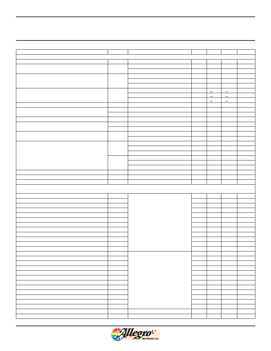
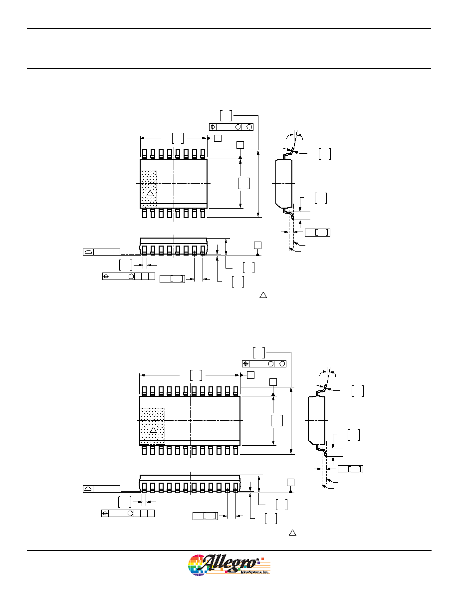
Package LW, 24-pin SOIC (A6279)
Package LW, 16-pin SOIC (A6278)
0.30
0.10
.012
.004
2.65
2.35
.104
.093
7.60
7.40
.299
.291
0.33
0.20
.013
.008
8∫
0∫
1.27
0.40
.050
.016
10.50
10.10
.614
.598
C
SEATING
PLANE
A
B
C
0.10 [.004]
16X
0.25 .010
0.51
0.31
.020
.012
16X
0.25 [.010] M C
A
B
10.63
9.97
.419
.393
0.25 [.010] M B M
1.27 .050
2
1
16
GAUGE PLANE
SEATING PLANE
Preliminary dimensions, for reference only
Dimensions in millimeters
U.S. Customary dimensions (in.) in brackets, for reference only
(reference JEDEC MS-013 AA)
Dimensions exclusive of mold flash, gate burrs, and dambar protrusions
Exact case and lead configuration at supplier discretion within limits shown
A Terminal #1 mark area
A
0.30
0.10
.012
.004
2.65
2.35
.104
.093
7.60
7.40
.299
.291
0.33
0.20
.013
.008
8∫
0∫
1.27
0.40
.050
.016
15.60
15.20
.614
.598
C
SEATING
PLANE
A
B
C
0.10 [.004]
24X
0.25 .010
0.51
0.31
.020
.012
24X
0.25 [.010] M C
A
B
10.63
9.97
.419
.393
0.25 [.010] M B M
1.27 .050
2
1
24
GAUGE PLANE
SEATING PLANE
Preliminary dimensions, for reference only
Dimensions in millimeters
U.S. Customary dimensions (in.) in brackets, for reference only
(reference JEDEC MS-013 AD)
Dimensions exclusive of mold flash, gate burrs, and dambar protrusions
Exact case and lead configuration at supplier discretion within limits shown
A Terminal #1 mark area
A

Serial-Input, Constant-Current Latched
LED Drivers with Open LED Detection
A6278
and
A6279
18
Allegro MicroSystems, Inc.
115 Northeast Cutoff, Box 15036
Worcester, Massachusetts 01615-0036 (508) 853-5000
www.allegromicro.com
The products described herein are manufactured under one or more of the following U.S. patents: 5,045,920; 5,264,783; 5,442,283; 5,389,889;
5,581,179; 5,517,112; 5,619,137; 5,621,319; 5,650,719; 5,686,894; 5,694,038; 5,729,130; 5,917,320; and other patents pending.
Allegro MicroSystems, Inc. reserves the right to make, from time to time, such de par tures from the detail spec i fi ca tions as may be required to
permit improvements in the per for mance, reliability, or manufacturability of its products. Before placing an order, the user is cautioned to verify that
the information being relied upon is current.
Allegro products are not authorized for use as critical components in life-support devices or sys tems without express written approval.
The in for ma tion in clud ed herein is believed to be ac cu rate and reliable. How ev er, Allegro MicroSystems, Inc. assumes no re spon si bil i ty for its
use; nor for any in fringe ment of patents or other rights of third parties which may result from its use.
Copyright©2005, 2006 Allegro MicroSystems, Inc.