Data Sheet
27627.100
The ATS610LSA and ATS611LSB gear-tooth sensors are opti-
mized Hall IC plus magnet modules that provide a user-friendly solu-
tion for digital gear-tooth sensing applications. Each module combines
in a compact high-temperature plastic package, a samarium-cobalt magnet, a
pole piece, and a differential Hall-effect IC that has been optimized to
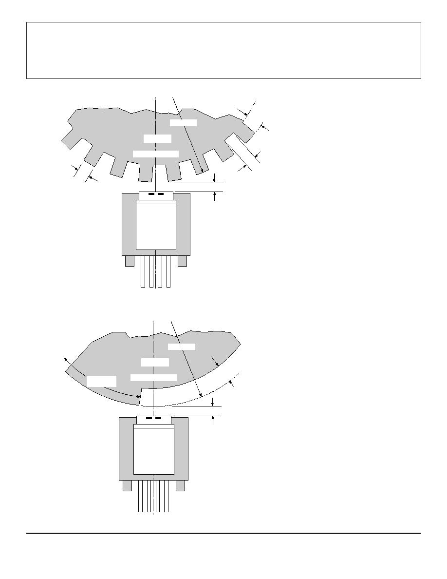
the magnetic circuit. These sensors can be easily used in conjunction
with a wide variety of gear or target shapes and sizes.
The ATS610LSA is designed to provide increased immunity to
false switching in applications that require the sensing of large-tooth
gears (e.g., crank angle or cam angle). The ATS611LSB is optimized
to sense fine-pitch gears over large working air gaps (e.g., transmis-
sion or ABS). These sensors are ideal for use in gathering speed,
position, and timing information using gear-tooth-based configurations.
The gear-sensing technology used for these sensor plus magnet
modules is Hall-effect based. The sensor incorporates a dual-element
Hall IC that switches in response to differential magnetic signals
created by the ferrous target. The circuitry contains a patented
track-and-hold peak-detecting circuit to eliminate magnet and system
offset effects. This circuit has the ability to detect relatively fast changes,
such as those caused by gear wobble and eccentricities, and provides
stable operation at extremely low rotation speeds.
Always order by complete part number, e.g., ATS610LSA .
continued next page...
FEATURES AND BENEFITS
Fully Optimized Differential Digital Gear-Tooth Sensor
Single-Chip Sensing IC for High Reliability
Extremely Low Timing Accuracy Drift with Temperature
Large Operating Air Gaps
Small Mechanical Size
Optimized Magnetic Circuit
Patented Peak-Detecting Filter:
<200
µ
s Power-On Time
<10 RPM Operation (single-tooth target)
Correct First-Edge Detection
Uses Small Value Ceramic Capacitors
Under-Voltage Lockout
Wide Operating Voltage Range
Defined Power-Up State
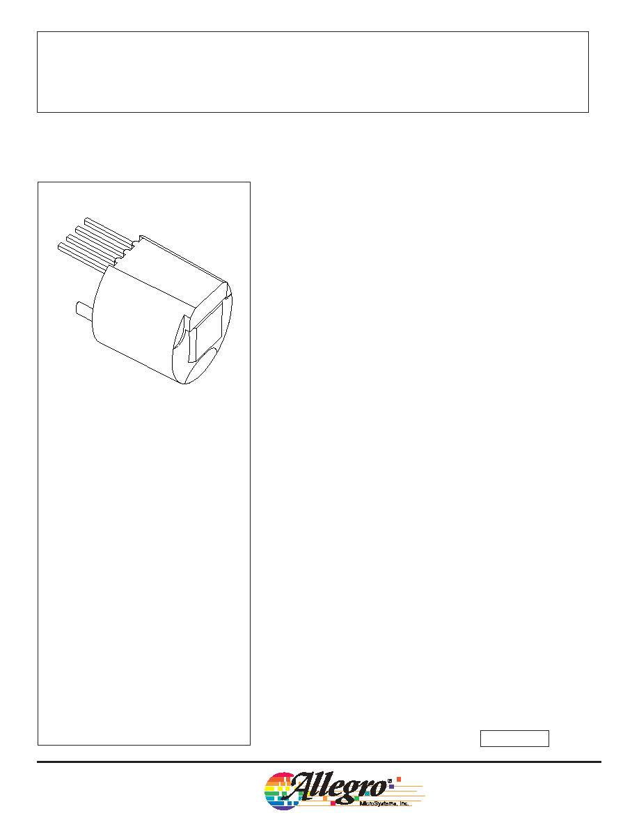
Dwg. AH-006
1
2
3
4
Pin 1 = Supply
Pin 2 = Output
Pin 3 = Capacitor
Pin 4 = Ground
DYNAMIC, PEAK-DETECTING, DIFFERENTIAL
HALL-EFFECT GEAR-TOOTH SENSORS
ABSOLUTE MAXIMUM RATINGS
over operating temperature range
Supply Voltage, V
CC
......................... 16 V*
Reverse Supply Voltage, V
RCC
....... -0.5 V
Output OFF Voltage, V
OUT
................. 18 V
Reverse Output Voltage, V
OUT
....... -0.5 V
Continuous Output Current, I
OUT
... 25 mA
Minimum External Capacitance,
C
3
............................................. 0.1
µ
F
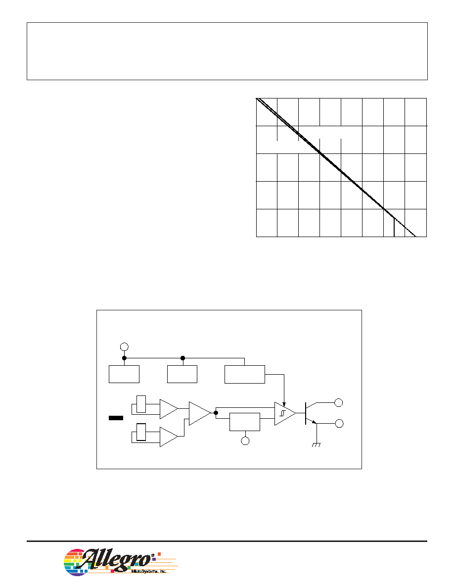
Package Power Dissipation,
P
D
.................................... See Graph
Operating Temperature Range,
T
A
........................... -40
∞
C to +150
∞
C*
Storage Temperature, T
S
............ +170
∞
C
* Operation at increased supply voltages with
external circuitry is described in Applications
Information. Devices for operation at increased
temperatures are available on special order.
ATS610LSA
AND
ATS611LSB
PRELIMINARY INFORMATION
(subject to change without notice)
August 28, 2002
ATS610LSA
AND
ATS611LSB
DYNAMIC, PEAK-DETECTING,
DIFFERENTIAL HALL-EFFECT
GEAR-TOOTH SENSORS
115 Northeast Cutoff, Box 15036
Worcester, Massachusetts 01615-0036 (508) 853-5000
2
Both sensors are packaged in miniature plastic
housings that have been optimized for size, ease of assembly,
and manufacturability. High operating temperature materi-
als are used in all aspects of construction. Devices for
operation at increased temperatures are also available on
special order.
ATS610LSA: Large-tooth, gear-position sensing --
crank angle, cam angle.
ATS611LSB: Fine-pitch, large air gap, gear-speed
sensing -- transmission, ABS.
600
400
200
40
80
120
160
0
AMBIENT TEMPERATURE IN
∞
∞
∞
∞
C
ALLOWABLE PACKAGE POWER DISSIPATION IN mW
Dwg. GH-065
"SA" PACKAGE
R
JA
= 147
∞
C/W
"SB" PACKAGE
R
JA
~ 150
∞
C/W
60
100
140
180
20
800
1000
FUNCTIONAL BLOCK DIAGRAM
OUTPUT
CAPACITOR
3
Dwg. FH-014
SUPPLY
GROUND
REG
+
≠
1
2
4
POWER-ON
LOGIC
E2
UVLO
+
≠
TRACK &
HOLD
MAGNET
E1
X
X
W
Copyright © 2002 Allegro MicroSystems, Inc.

ATS610LSA
AND
ATS611LSB
DYNAMIC, PEAK-DETECTING,
DIFFERENTIAL HALL-EFFECT
GEAR-TOOTH SENSORS
115 Northeast Cutoff, Box 15036
Worcester, Massachusetts 01615-0036 (508) 853-5000
4
ATS610LSA OPERATION over operating voltage and temperature range with reference target
(unless otherwise specified).
ATS611LSB OPERATION over operating voltage and temperature range with reference target
(unless otherwise specified).
* The one-tooth (180
∞
) target is not recommended for use with the ATS611LSB.
Limits
Characteristic
Symbol
Test Conditions
Min.
Typ.
Max.
Units
Air Gap Range
AG
Operating,
0.4
≠
2.25
mm
Target Speed > 20 RPM
Minimum Air Gap
AG
min
Operating, One-Tooth (180
∞
)
≠
0.25
≠
mm
Target, Target Speed = 1000 RPM
Maximum Air Gap
AG
max
Operating, One-Tooth (180
∞
)
≠
2.75
≠
mm
Target, Target Speed = 1000 RPM
Timing Accuracy
t
Target Speed = 1000 RPM,
≠
±
0.5
±
1.0
∞
0.4 mm
AG
2 mm
Limits
Characteristic
Symbol
Test Conditions
Min.
Typ.
Max.
Units
Air Gap Range
AG
Operating,
0.4
≠
2.5
mm
Target Speed > 20 RPM
Minimum Air Gap
AG
min
Operating, One-Tooth (180
∞
)
≠
0.75
≠
mm
Target*, Target Speed = 1000 RPM
Maximum Air Gap
AG
max
Operating, One-Tooth (180
∞
)
≠
3.25
≠
mm
Target*, Target Speed = 1000 RPM
Timing Accuracy
t
Target Speed = 1000 RPM,
≠
±
0.5
±
1.0
∞
0.4 mm
AG
2 mm