 | –≠–ª–µ–∫—Ç—Ä–æ–Ω–Ω—ã–π –∫–æ–º–ø–æ–Ω–µ–Ω—Ç: ATS645LSH | –°–∫–∞—á–∞—Ç—å:  PDF PDF  ZIP ZIP |
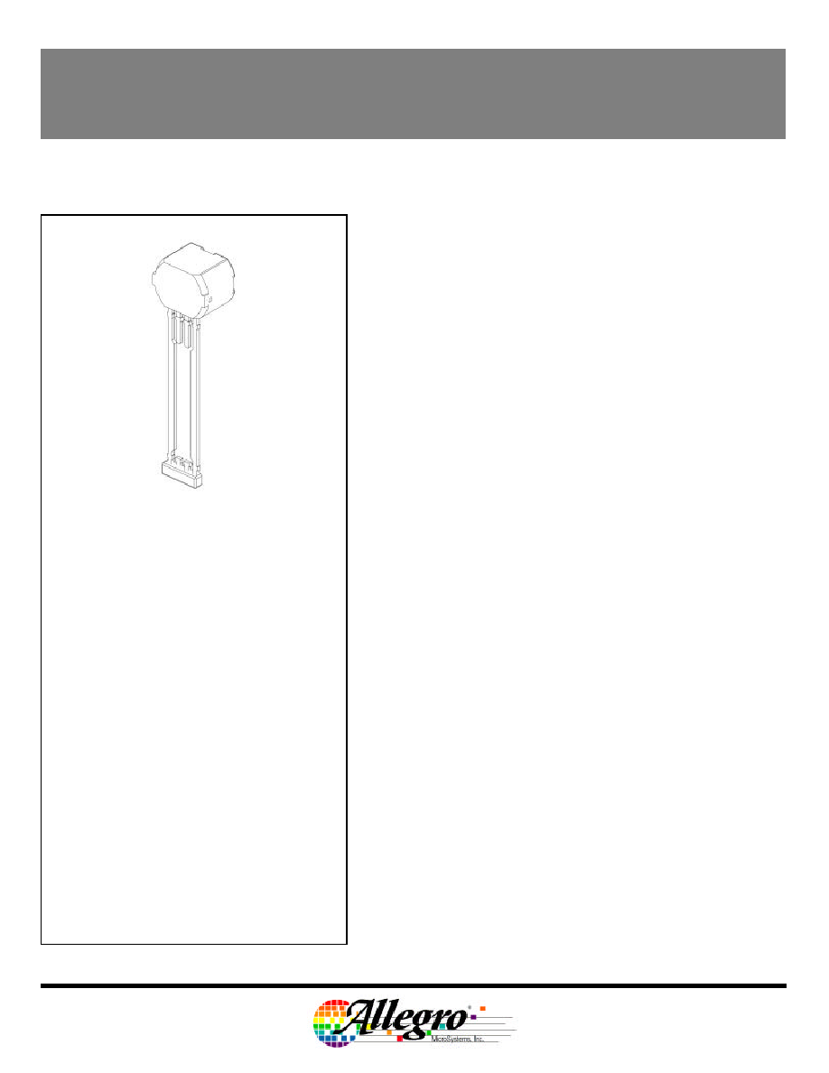
ATS645LSH
Preliminary ≠ Subject to Change
PRELIMINARY DATASHEET
(subject to change without notice)
True Zero Speed
Miniature Gear Tooth Sensor
Pin 1: Supply
Pin 2: No connection
Pin 3: Test pin
Pin 4: Ground
The ATS645LSH is an optimized Hall effect sensing integrated
circuit and magnet combination that provides a user-friendly
solution for true zero-speed digital gear-tooth sensing in two-wire
applications. The sensor consists of a single-shot molded plastic
package that includes a samarium cobalt magnet, a pole piece, and
a Hall effect IC that has been optimized to the magnetic circuit.
This small package can be easily assembled and used in
conjunction with a wide variety of gear shapes and sizes.
The integrated circuit incorporates a dual element Hall effect
sensor and signal processing that switches in response to
differential magnetic signals created by ferrous gear teeth. The
circuitry contains a sophisticated digital circuit to eliminate magnet
and system offsets and to achieve true zero speed operation (ref
U.S. Patent 5,917,320). A-D and D-A converters are used to adjust
the device gain at power up and to allow air gap independent
switching.
The regulated current output is configured for two wire
applications and the sensor is ideally suited for obtaining speed and
duty cycle in ABS and transmission application gear-tooth-based
configurations.
ABSOLUTE MAXIMUM RATINGS
Supply Voltage,
V
CC
. . . . . . . . . . . . . . . . . . . . . . . . . 26.5 V*
Reverse Supply Voltage,
V
R
. . . . . . . . . . . . . . . . . . . . . . . . . . . . ≠18 V
Operating Temperature Range,
T
A
. . . . . . . . . . . . . . . . . ≠40
∞
C to 150
∞
C*
Storage Temperature,
T
S
. . . . . . . . . . . . . . . . . . . . . . . . . . . 170
∞
C
Package Power Rating,
JA
. . . . . . . . . . . . . . . . . . . . . . . . 126
∞
C/W
Maximum Junction Temperature,
T
Jmax
. . . . . . . . . . . . . . . . . . . . . 165
∞
C
*
Operation at increased supply voltages with external
circuitry is described in the Applications Information
.
FEATURES
s
Fully optimized differential digital gear tooth sensor
s
Single chip sensing IC for high reliability
s
Internal current regulator for 2 wire operation
s
Small mechanical size (8 mm dia x 5.5 mm length)
s
Air gap independent switch points
s
Digital output representing gear profile
s
Precise duty cycle signal with temperature
s
Large operating air gaps
s
Automatic Gain Control (AGC)
s
Automatic Offset Adjustment circuit
s
True zero speed operation
s
Under-voltage lockout
s
Wide operating voltage range
s
Defined power-on state
ATS645LSH-DS Rev. 1

ATS645LSH ≠ Preliminary ≠ Allegro Confidential
TRUE ZERO SPEED DIFFERENTIAL PEAK DETECTOR
Revision 1.2; MHN; 07.Aug.02
Page
2 of 12
115 Northeast Cutoff, Box 15036
Worcester, Massachusetts 01615-0036 (508) 853-5000
Copyright © 1993, 1995 Allegro MicroSystems, Inc.
CHARACTERISTICS
Valid over operating temperature range and Supply Voltage within specification unless otherwise noted.
Limits
Characteristics
Symbol
Test Conditions
Min.
Typ.
Max.
Units
ELECTRICAL CHARACTERISTICS
Supply Voltage
V
CC
Operating, T
J
< 165
∞
C
4.0
24
V
Under Voltage Lockout
V
CC(UV)
V
CC
0
5 V
-
-
<Vcc
Min
V
1
Supply Zener Clamp Voltage
V
Z
I
ZT
= 1 mA
28
32
-
V
Max Zener Pulse Current
I
Z
t=20mS Pulse Mode
-
-
50
mA
Supply Zener Resistance
R
Z
-
50
-
Low Current State: Icc
Low
4.0
6
8.0
mA
Supply Current
ATS645LSH ≠ I1
I
CC
High Current State: Icc
High
12.0
14.0
16.0
mA
Low Current State: Icc
Low
5.9
7
8.4
mA
Supply Current
ATS645LSH ≠ I2
I
CC
High Current State: Icc
High
11.8
14.0
16.8
mA
POWER-ON STATE CHARACTERISTICS
Power-On State
S
PO
V
CC
0
5 V
-
Icc
High
-
-
2
Power-On Time
t
on
Gear speed < 100 rpm
-
1
2
ms
OUTPUT STAGE
Output Current Slew Rate
I
R
Icc
High
ý
Icc
Low
, Icc
Low
ý
Icc
High
,
R
S
= 100
, C
S
= 10 pF, 10 to 90%
10
mA/µs
1
The zener is tested using a pulse method and is designed for transient protection, continuous operation may destroy the device.
2
Power On Time is the time required to complete internal offset adjust. It does not include automatic gain control, which requires
three tooth valley transitions to complete and is therefore RPM dependent.
ATS645LSH ≠ Preliminary ≠ Allegro Confidential
TRUE ZERO SPEED DIFFERENTIAL PEAK DETECTOR
Revision 1.2; MHN; 07.Aug.02
Page
3 of 12
115 Northeast Cutoff, Box 15036
Worcester, Massachusetts 01615-0036 (508) 853-5000
Copyright © 1993, 1995 Allegro MicroSystems, Inc.
Operating Characteristics: Valid with Reference Target unless otherwise specified
Limits
Characteristics
Symbol
Test Conditions
Min.
Typ.
Max.
Units
SWITCH POINT CHARACTERISTICS
Rotation Speed
S
max
Using Reference Target over Operating
Air Gap Range
0
8K
RPM
Analog Signal Bandwidth
f-3db
-3dB Point
20
40
KHz
1
Operate Point
Bop
Icc
High
ý
Icc
Low
Positive Peak referenced, AG < AG
max
-
100
150
mV
1
Release Point
Brp
Icc
Low
ý
Icc
High
Negative Peak referenced, AG < AG
max
-
100
150
mV
Calibration
Initial Calibration
C
I
Number of Rising Mechanical Edges for
Accurate Edge Detection
3
Edges
DAC Characteristics
Allowable User Induced
Differential Offset
Output switching only; may not meet
data sheet specifications
-60
60
G
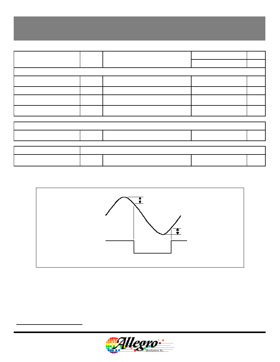
SWITCH POINT DETAIL
1
Bop and Brp should be adjustable with metal mask changes, limits max air gap but improves vibration immunity.
Bop
Brp
Input
Differential
Signal
Device
Output
Current
Pin 3 Differential Signal (not magnetic signal)

ATS645LSH ≠ Preliminary ≠ Allegro Confidential
TRUE ZERO SPEED DIFFERENTIAL PEAK DETECTOR
Revision 1.2; MHN; 07.Aug.02
Page
4 of 12
115 Northeast Cutoff, Box 15036
Worcester, Massachusetts 01615-0036 (508) 853-5000
Copyright © 1993, 1995 Allegro MicroSystems, Inc.
Operating Characteristics:
Valid only if magnetic offset is within the Dynamic Offset Compensation DAC Range as specified above
Limits
Characteristics
Symbol
Test Conditions
Min.
Typ.
Max.
Units
OPERATING CHARACTERISTICS: Using Reference Target and Valid Over Operating Temperature Range
1
Operational Air Gap Range
Op
AG
Duty cycle within specification
0.5
2.75
mm
Switching Air Gap Range
Op
MaxAG
Output Switching: Duty cycle Not in
Specification
3
-
-
mm
Duty Cycle Variation
DC
Wobble < 0.5mm
Typical value at 1.5mm air gap
Valid over operating air gap range
37
53
57
%
2
Operating Signal Range
Sig
Duty cycle within Specification
Wobble < 0.5mm
30
-
1000
G
3
Minimum Operating Signal
Sig
Min
Output Switching: Duty Cycle Not in
Specification
20
-
-
G
1
Operating air gap is dependent on the available magnetic field. The available field is target geometry and materiel
dependent and should be independently characterized. The field available from the reference target is given in the
reference gear parameter section of the datasheet
2
In order to remain in specification the magnetic signal must be larger than the minimum value specified, this includes the
effect of target wobble.
3
Duty cycle is not guaranteed to be in specification. Reference the Duty Cycle vs. Air Gap Over Temperature graph in
the typical operating characteristics section of this document.
ATS645LSH ≠ Preliminary ≠ Allegro Confidential
TRUE ZERO SPEED DIFFERENTIAL PEAK DETECTOR
Revision 1.2; MHN; 07.Aug.02
Page
5 of 12
115 Northeast Cutoff, Box 15036
Worcester, Massachusetts 01615-0036 (508) 853-5000
Copyright © 1993, 1995 Allegro MicroSystems, Inc.
Reference Gear Parameters
REFERENCE GEAR DIMENSIONS (60-0)
Diameter
G
d
-
120
-
mm
Thickness
G
t
-
6
-
mm
Tooth Width
T
w
-
3
-
mm
Valley Width
V
w
-
3
-
mm
Valley Depth
V
d
-
3
-
mm
Materiel
Low Carbon Steel
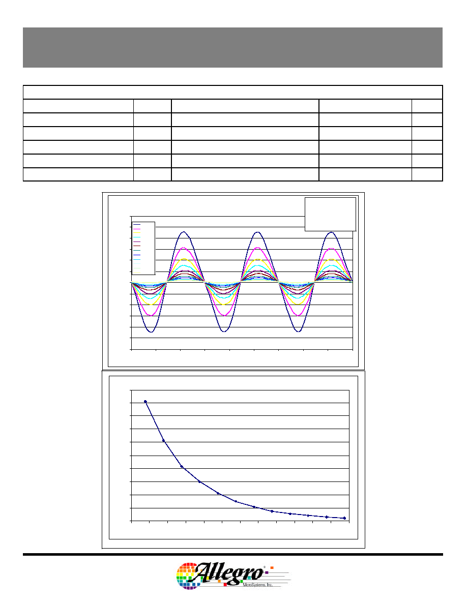
Reference Target Peak to Peak vs. Air Gap
0
50
100
150
200
250
300
350
400
450
500
0.75
1
1.25
1.5
1.75
2
2.25
2.5
2.75
3
3.25
3.5
3.75
Air Gap [mm]
P-P [Gauss]
Flux Density vs. Position
Reference Target
-300
-250
-200
-150
-100
-50
0
50
100
150
200
250
300
244
246
248
250
252
254
256
258
260
262
Position (∫)
Flux Density (Gauss)
0.94mm
1.19mm
1.44mm
1.69mm
1.94mm
2.19mm
2.44mm
2.69mm
2.94mm
3.19mm
3.44mm
3.69mm
Target Description:
Tooth Width: 3.25mm
Diameter: 120mm
Valley Width: 3.10mm
Tooth Thickness: 6mm
Valley Depth: 3mm