 | ÐлекÑÑоннÑй компоненÑ: ATS651LSH | СкаÑаÑÑ:  PDF PDF  ZIP ZIP |
Äîêóìåíòàöèÿ è îïèñàíèÿ www.docs.chipfind.ru
ATS651LSH
651LSH-DS
Worcester, Massachusetts 01615-0036 (508) 853-5000
115 Northeast Cutoff, Box 15036
www.allegromicro.com
Allegro MicroSystems, Inc.
AB SO LUTE MAX I MUM RAT INGS
Supply Voltage*, V
CC
.........................................28 V
Reverse-Supply Voltage, V
RCC
........................ 18 V
Reverse-Output Voltage, V
ROUT
....................50 mA
Temperatures
Operating
Ambient,
T
A
................. 40ºC to 150ºC
Junction,
T
J(MAX)
.......................................165ºC
Storage,
T
S
................................. 65ºC to 170ºC
*Refer to Power Derating section
Two-Wire Self-Calibrating Differential
Speed and Direction Sensor with Vibration Immunity
Use the following complete part numbers when ordering:
Package SH
Features and Benefits
1. VCC
2. Test pin, Channel 1
3. Test pin, Channel 2
4. GND
1 2
3 4
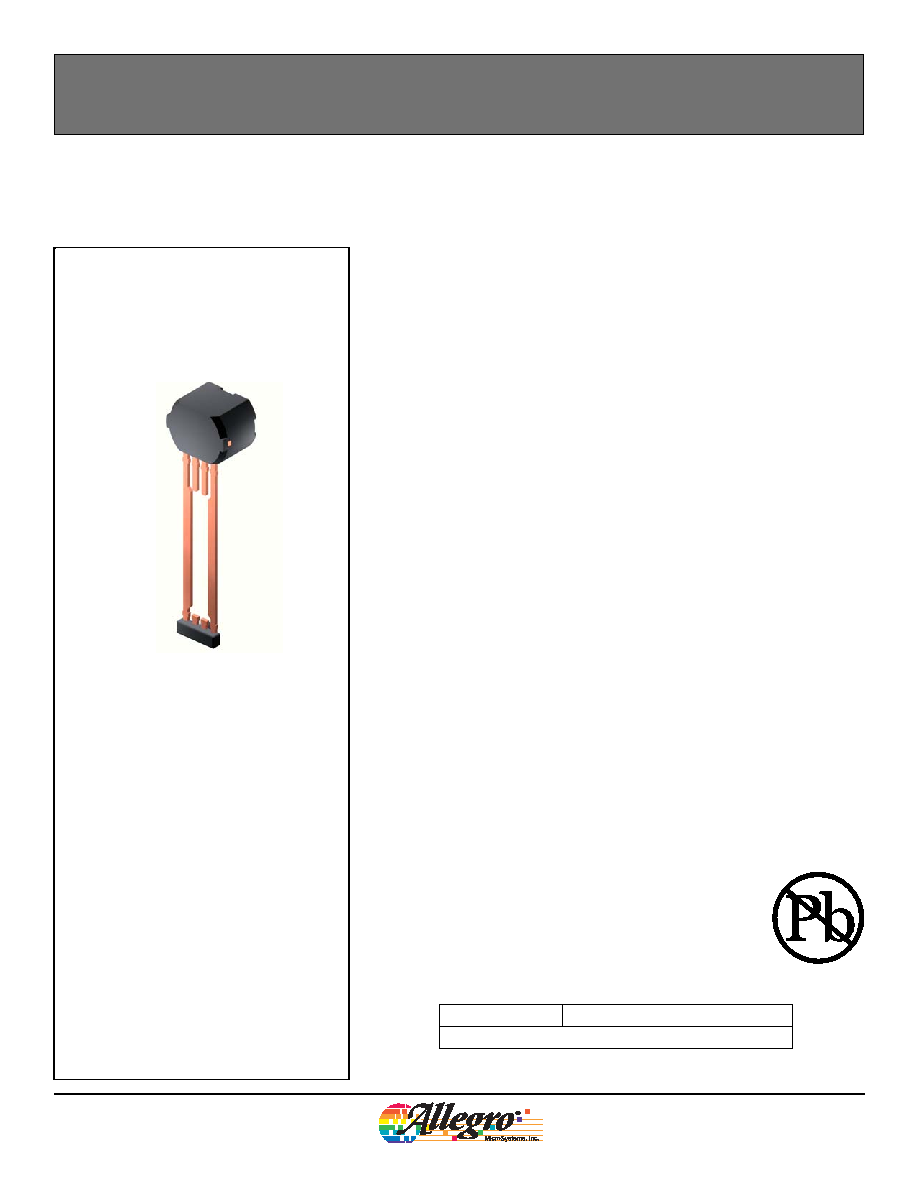
The ATS651LSH is a mechatronics component with an integrated Hall-effect sen-
sor and magnet, providing an easy-to-use solution for speed and direction sensing
applications. The solid thermoset molded plastic package contains a samarium
cobalt magnet and a Hall-effect IC optimized to the magnetic circuit. This sensor
module has been designed specifically for high reliability in the harsh automotive
environment.
The IC employs patented algorithms for the special operational requirements of
transmission applications. This two-wire device communicates the speed and
direction of a ferrous target via a pulse width modulation (PWM) output protocol.
The ATS651LSH is particularly adept at handling vibration without sacrificing
maximum air gap capability or creating an erroneous "direction" pulse. Even the
higher angular vibration caused by engine cranking is completely rejected by
the device. The advanced vibration detection algorithm systematically calibrates
the sensor on the true rotation signals from the first three and a half teeth, not on
vibration, thus always guaranteeing an accurate signal in running mode.
Patented running mode algorithms also protect against air gap changes, whether
or not the target is in motion. Direction information is always available on the first
magnetic edge after a direction change. Advanced signal processing and innova-
tive algorithms make the ATS651LSH an ideal solution for a wide range of speed
and direction sensing needs.
The device package is lead (Pb) free, with 100% matte tin plated leadframe.
Part Number
Packing*
ATS651LSHTN-T
13-in. reel, 800 pieces/reel
*Contact Allegro for additional packing options.
· Rotational direction detection
· Fully optimized digital differential gear-tooth sensor
· Single-chip sensing IC for high reliability
· Small mechanical size (8 mm diameter × 5.5 mm vertical, flat-to-flat)
· Internal current regulator for 2-wire operation
· Automatic Gain Control (AGC) and reference adjust circuit
· 3-bit factory trimmed for tight pulse width accuracy
· True zero-speed operation
· Wide operating voltage range
· Undervoltage lockout
· Defined power-on state
· ESD and reverse polarity protection
2
651LSH-DS
Worcester, Massachusetts 01615-0036 (508) 853-5000
115 Northeast Cutoff, Box 15036
www.allegromicro.com
Allegro MicroSystems, Inc.
Two-Wire Self-Calibrating Differential Speed and Direction Sensor with Vibration Immunity
ATS651LSH
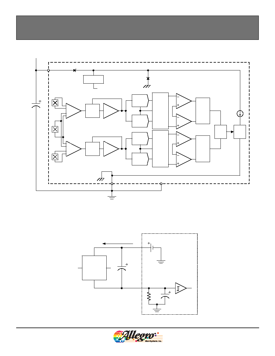
Functional Block Diagram
Current
Output
Adjust
GND
VCC
0.01F
C
BYPASS
V+
Voltage
Regulator
TEST
Hall
Amp
PDAC
NDAC
Reference
Generator
& Updates
PThresh
NThresh
Threshold
Logic
(Recommended)
Speed
and
Direction
Logic
AGC
Offset
Adjust
Hall
Amp
PDAC
NDAC
Reference
Generator
& Updates
PThresh
NThresh
Threshold
Logic
AGC
Offset
Adjust
Typical Application Diagram
2
ATS651
1
3
4
0.01
F
100
ECU
I
CC(HIGH)
/I
CC(LOW)
R
SENSE
C
SENSE
C
BYPASS
Note: Pins 2 and 3 may be connected to pin 4.
However, I
CC
is increased in that configuration.
3
651LSH-DS
Worcester, Massachusetts 01615-0036 (508) 853-5000
115 Northeast Cutoff, Box 15036
www.allegromicro.com
Allegro MicroSystems, Inc.
Two-Wire Self-Calibrating Differential Speed and Direction Sensor with Vibration Immunity
ATS651LSH
ELECTRICAL CHARACTERISTICS Valid for 40°C T
A
150°C, T
J
165°C, unless otherwise noted
Characteristics
Symbol
Test Conditions
Min.
Typ.
Max.
Units
Supply Voltage
V
CC
Running, T
J
165°C
4.3
24
V
Undervoltage Lockout
V
CC(UV)
V
CC
= 5
0 V
4.3
V
Reverse Supply Current
I
RCC
V
CC
= 18 V
10
mA
Supply Zener Clamp Voltage
V
Z
I
CC(Low)max
+ 3 mA
28
40
V
Supply Zener Resistance
R
Z
20
Output Current Slew Rate
SR
I
I
(High)
I
(Low)
, I
(Low)
I
(High)
R
SENSE
= 100 , C
SENSE
= 10 pF, 10 to 90% points
2
16
mA/
s
Power-On State
POS
I
ON
state
I
CC(Low)
mA
Power-On Time
1
t
PO
Gear speed < 100 rpm
1
ms
Supply Current
I
CC(Low)
Low-current state
4
7
9
mA
I
CC(High)
High-current state
12
14.5
17
mA
Supply Current Difference
I
CC
I
CC(High)
- I
CC(Low);
difference between high-current state level
and low-current state level
5.3
mA
CALIBRATION
Direction Information
2
N
Dir
First output transition
8
Edge
Speed Information
2
N
Spd
First output transition
8
Edge
Direction Change Detection
3
N
CD
Running mode direction change
1
Edge
Signal Variation
4
(At calibration)
E
CAL
Over four edges
±0.3
mm
DAC CHARACTERISTICS
Dynamic Offset Cancellation
5
As shipped
±60
G
1
Power-On Time is the time required to complete the internal automatic offset adjust; the DACs are then ready for peak acquisition.
2
Edge count is based on mechanical edges. First output edge is available on or before N
Dir
or N
Spd
edges.
3
Edge count is based on mechanical edges. On the N
CD
edge, direction and speed information is valid.
4
If the peak-to-peak amplitude of the signal varies more than the specified amount during the direction verification process, then additional edges may
be required for calibration.
5
The device will compensate for magnetic and installation offsets up to ±60 gauss. Offsets greater than ±60 gauss may cause inaccuracies in the
output.
OPERATING CHARACTERISTICS Using Reference Target 60-0 and valid over operating temperature range
Characteristics
Symbol
Test Conditions
Min.
Typ.
Max.
Units
Operational Air Gap Range
*
AG
OP
Within specification
0.5
2.8
mm
Operating Signal Range
Sig
Within specification
30
1200
G
*
Operational Air Gap Range is dependent on the available differential magnetic field. The available field is dependent on target geometry and material,
and should be independently characterized. The field available from the Reference Target is given in the Reference Target Parameters section of this
datasheet.
Device Characteristics Tables
Continued on the next page...
4
651LSH-DS
Worcester, Massachusetts 01615-0036 (508) 853-5000
115 Northeast Cutoff, Box 15036
www.allegromicro.com
Allegro MicroSystems, Inc.
Two-Wire Self-Calibrating Differential Speed and Direction Sensor with Vibration Immunity
ATS651LSH
SWITCHING CHARACTERISTICS Valid for 40°C T
A
150°C, T
J
165°C, unless otherwise noted
Characteristics
Symbol
Test Conditions
Min.
Typ.
Max.
Units
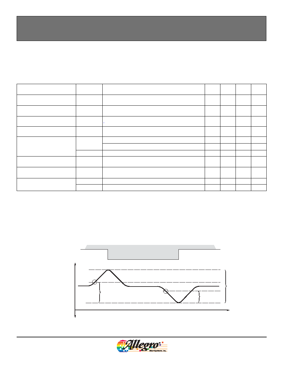
Operate Point
B
OP
% of peak-to-peak referenced from PDAC to NDAC,
AG
OP
< AG
OP(max)
58
%
Release Point
B
RP
% of peak-to-peak referenced from PDAC to NDAC,
AG
OP
< AG
OP(max)
42
%
Axial/Radial Runout
1
(Multiple teeth)
RO
A/R
±1.75
mm
Sudden Air Gap
(Single tooth)
AG
SAG
Instantaneous air gap change (<500 Hz)
±0.4
mm
Incremental Air Gap
(Consecutive edges)
AG
IR+
Air gap change between edges @ >8 kHz
±0.1
mm
Air gap change between edges @ 8-4 kHz
±0.15
mm
AG
IR-
Air gap change between edges @ <4 kHz
±0.2
mm
Vibration Immunity
(At power-on)
ROT
VIBS
Rotation allowed due to vibration with temperature change
less than 10°C
±0.75
(°)
Vibration Immunity
2
(Running)
ROT
VIBR
Rotation allowed due to vibration with temperature change
less than 10°C
±0.35
(°)
Maximum Operating Frequency
3
f
L
Rotation Left (target rotation CCW, pin 1 to pin 4), t
LD
= 38 s
6
kHz
f
R
Rotation Right (target rotation CW, pin 4 to pin 1), t
LD
= 38 s
12
kHz
1
Inclusive of all Sudden Air Gap and Incremental Air Gap changes during operation.
2
Device may output one reverse pulse at the start of vibration.
3
Maximum Operating Frequency may be increased if the customer can resolve Minimum Low-State Duration levels down to the specified value.
ATS651LSH Switchpoints
100 %
Differential Magnetic
Flux Density, B
Valley
Tooth
B+
B
t
B
OP
%
B
OP
B
RP
B
RP
%
Device Characteristics Tables (Continued)
Continued on the next page...
5
651LSH-DS
Worcester, Massachusetts 01615-0036 (508) 853-5000
115 Northeast Cutoff, Box 15036
www.allegromicro.com
Allegro MicroSystems, Inc.
Two-Wire Self-Calibrating Differential Speed and Direction Sensor with Vibration Immunity
ATS651LSH
Protocol Pulse Characteristics Valid for 40°C T
A
150°C (T
J
165°C), unless otherwise noted
Characteristics
Symbol
Test Conditions
Min.
Typ.
Max.
Units
Minimum Low-State Duration*
t
LD
Falling edge to subsequent rising edge.
10
s
Pulse Width Right
t
W(R)
38
45
52
s
Pulse Width Left
t
W(L)
76
90
104
s
Protocol Pulse Width Tolerance
E
PPW
Reference Target
15
15
%
*Maximum Operating Frequency may be increased if the application controller can resolve Minimum Low-State Duration levels down to the specified
value.
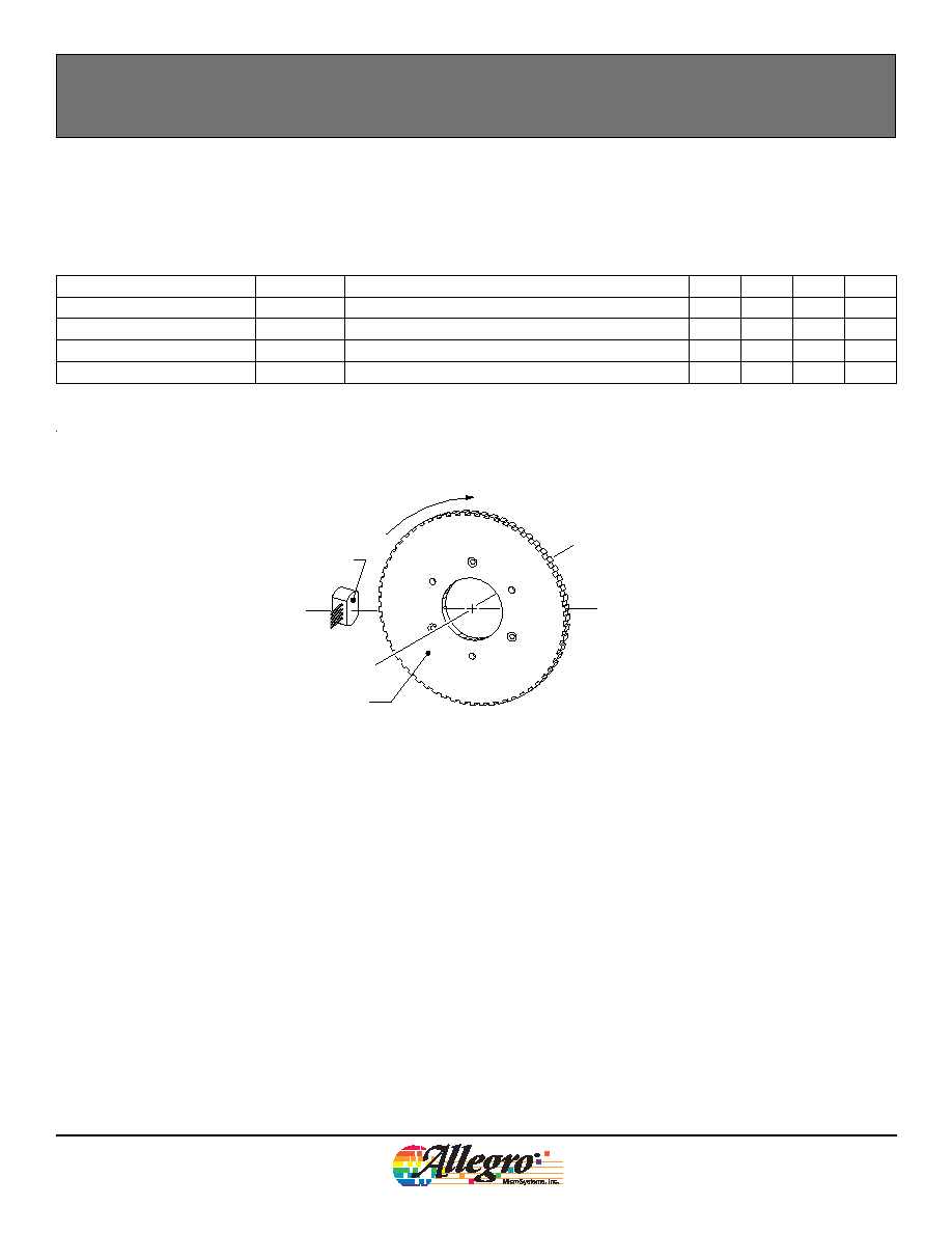
Target Rotating in Clockwise (CW, Right) Direction
Rotating Target
Pin1
Pin4
of Sensor
Branded Face
Device Characteristics Tables (Continued)