Data Sheet
28210C*
UNIPOLAR STEPPER-MOTOR
TRANSLATOR/PWM DRIVER
Combining
low-power CMOS logic with high-current, high-voltage
power FET outputs, the SLA7051M translator/driver provides complete
control and drive for a two-phase unipolar stepper motor with internal
fixed off time, pulse-width modulation (PWM) control of the output
current in a power multi-chip module (PMCMTM).
The CMOS logic section provides the sequencing logic, direction,
full/half-step control, synchronous/asynchronous PWM operation, and a
"sleep" function. The minimum CLOCK input is an ideal fit for
applications where a complex µP is unavailable or overburdened. TTL
or LSTTL may require the use of appropriate pull-up resistors to ensure
a proper input-logic high. For PWM current control, the maximum
output current is determined by the user's selection of a reference
voltage and sensing resistor. The NMOS outputs are capable of sinking
up to 2 A and withstanding 46 V in the off state. Ground-clamp and
flyback diodes provide protection against inductive transients
. Special
power-up sequencing is not required.
Full-step (2 phase) and half-step operation are externally selectable.
Two-phase drive energizes two adjacent phases in each detent position
(AB-BC-CD-DA). This sequence mode offers an improved torque-
speed product, greater detent torque, and is less susceptable to motor
resonance. Half-step excitation alternates between the one-phase and
two-phase modes (A-AB-B-BC-C-CD D-DA), providing an eight-step
sequence.
The SLA7051M is supplied in an 18-pin single in-line power-tab
package with leads formed for vertical mounting (suffix LF871) or
horizontal mounting (suffix LF872). The tab is at ground potential and
needs no insulation. For high-current or high-frequency applications,
external heat sinking may be required. This device is rated for continu-
ous operation between -20∞C and +85∞C.
F
EATURES
2 A Output Rating
Internal Sequencer for Full or Half-Step Operation
PWM Constant-Current Motor Drive
Cost-Effective, Multi-Chip Solution
100 V, Avalanche-Rated NMOS
Low
r
DS(on)
NMOS Outputs (300 m
typical)
Advanced, Improved Body Diodes
Half-Step and Full-Step Unipolar Drive
Inputs Compatible with 3.3 V or 5 V Control Signals
Sleep Mode
Internal Clamp Diodes
Always order by complete part number, e.g., SLA7051MLF871 .
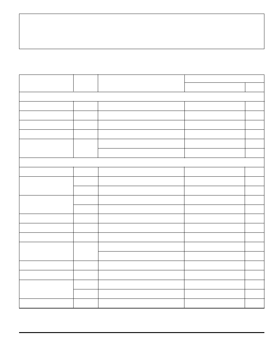
A
BSOLUTE
M
AXIMUM
R
ATINGS
Driver Supply Voltage, V
BB
................ 46 V
Load Supply Voltage, V
M
................... 46 V
Output Current, I
O
........................... 2.0 A*
Logic Supply Voltage, V
DD
................ 7.0 V
Logic Input Voltage Range,
V
I
.......................... -0.3 V to V
DD
+ 0.3 V
Sense Voltage, V
S
........................ ±2.0 V
Reference Input Voltage Range,
V
REF ..................................
-0.3 V to V
DD
+ 0.3 V
Package Power Dissipation,
P
D
....................................... See Graph
Junction Temperature, T
J
............. +150∞C
Operating Temperature Range,
T
A
................................. -20∞C to +85∞C
Storage Temperature Range,
T
S
............................... -30∞C to +150∞C
* Output current rating may be limited by duty cycle,
ambient temperature, and heat sinking. Under any set of
conditions, do not exceed the specified current rating or
junction temperature.
Internal filtering provides protection against transients
during the first 1 µs of the current-sense pulse.
SLA7051M
Motor
Driver
Sanken Power Devices
from Allegro MicroSystems

115 Northeast Cutoff, Box 15036
Worcester, Massachusetts 01615-0036 (508) 853-5000
SLA7051M
UNIPOLAR STEPPER-MOTOR
TRANSLATOR/PWM DRIVER
2
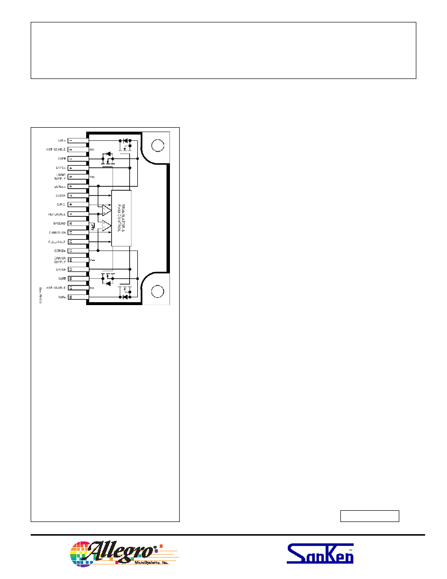
Motor
Driver
Functional block diagram
Copyright © 2002, 2004 Allegro MicroSystems, Inc.
Recommended operating conditions
Load Supply Voltage, V
BB
................................. 10 to 44 V
Logic Supply Voltage, V
DD
........................... 3.0 V to 5.5 V
Reference Input Voltage, V
REF
.................... 0.1 V to 1.0 V
Tab Temperature (no heat sink), T
T
...................... <100∞C

SLA7051M
UNIPOLAR STEPPER-MOTOR
TRANSLATOR/PWM DRIVER
www.allegromicro.com
5
Motor
Driver
Functional description
Device operation.
The SLA7051M is a complete
stepper-motor driver with built-in translator for easy
operation with minimal control lines. It is designed to
operate unipolar stepper motors in full-step or half-step
modes. The current in each pair of outputs, all n-channel
MOSFETs, is regulated with internal fixed off-time pulse-
width modulated (PWM) control circuitry.
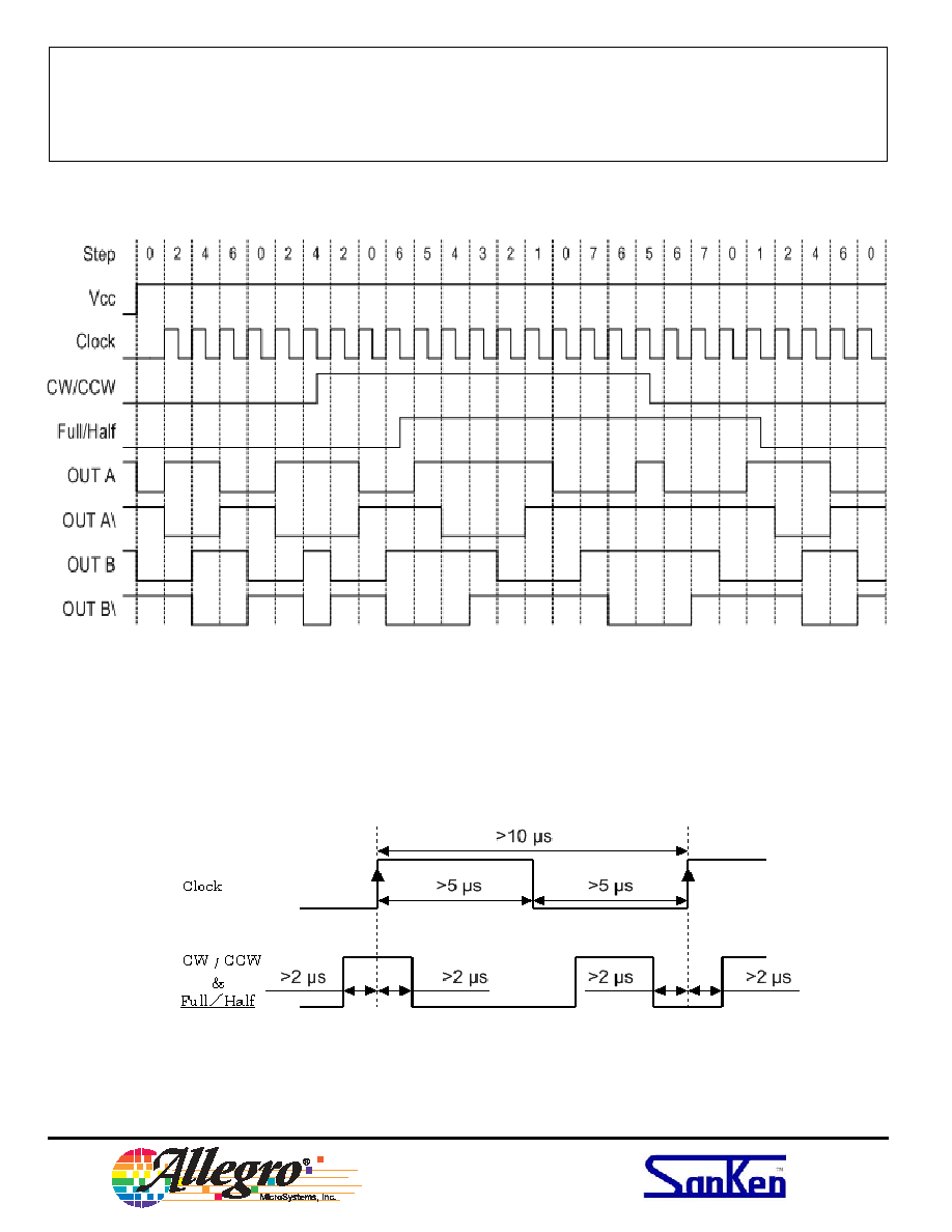
When a step command signal occurs on the clock input
the translator automatically sequences to the next step.
Clock (step) input.
A low-to-high transition on the
clock input sequences the translator and advances the
motor one increment. The hold state is done by stopping
the CLOCK input regardless of the input level
Full/half-step select.
This logic-level input sets the
translator step mode. A logic low is two-phase, full step; a
logic high is half step. Changes to this input do not take
effect until the rising edge of the clock input.
CW/CCW (direction) input.
This logic-level input sets
the translator step direction. Changes to this input do not
take effect until the rising edge of the clock input.
Internal PWM current control.
Each pair of outputs is
controlled by a fixed off-time PWM current-control circuit
that limits the load current to a desired value (I
TRIP
).
Initially, an output is enabled and current flows through
the motor winding and R
S
. When the voltage across the
current-sense resistor equals the reference voltage, the
current-sense comparator resets the PWM latch, which
turns off the driver for the fixed off time during which the
load inductance causes the current to recirculate for the off
time period. The driver is then re-enabled and the cycle
repeats.
Synchronous operation mode.
This function pre-
vents occasional motor noise during a "hold" state, which
normally results from asynchronous PWM operation of
both motor phases. A logic high at the SYNC input is
synchronous operation; a logic low is asynchronous
operation. The use of synchronous operation during
normal stepping is not recommended because it produces
less motor torque and can cause motor vibration due to
stair-case current.
Sleep mode.
Applying a voltage greater than 2 V to the
REF pin disables the outputs and puts the motor in a free
state (coast). This function is used to minimize power
consumption when not in use. It disables much of the
internal circuitry including the output MOSFETs and
regulator. When coming out of sleep mode, wait 100 µs
before issuing a step command to allow the internal
circuitry to stabilize.