 | ÐлекÑÑоннÑй компоненÑ: SWB | СкаÑаÑÑ:  PDF PDF  ZIP ZIP |
07-SS/TS Series

19
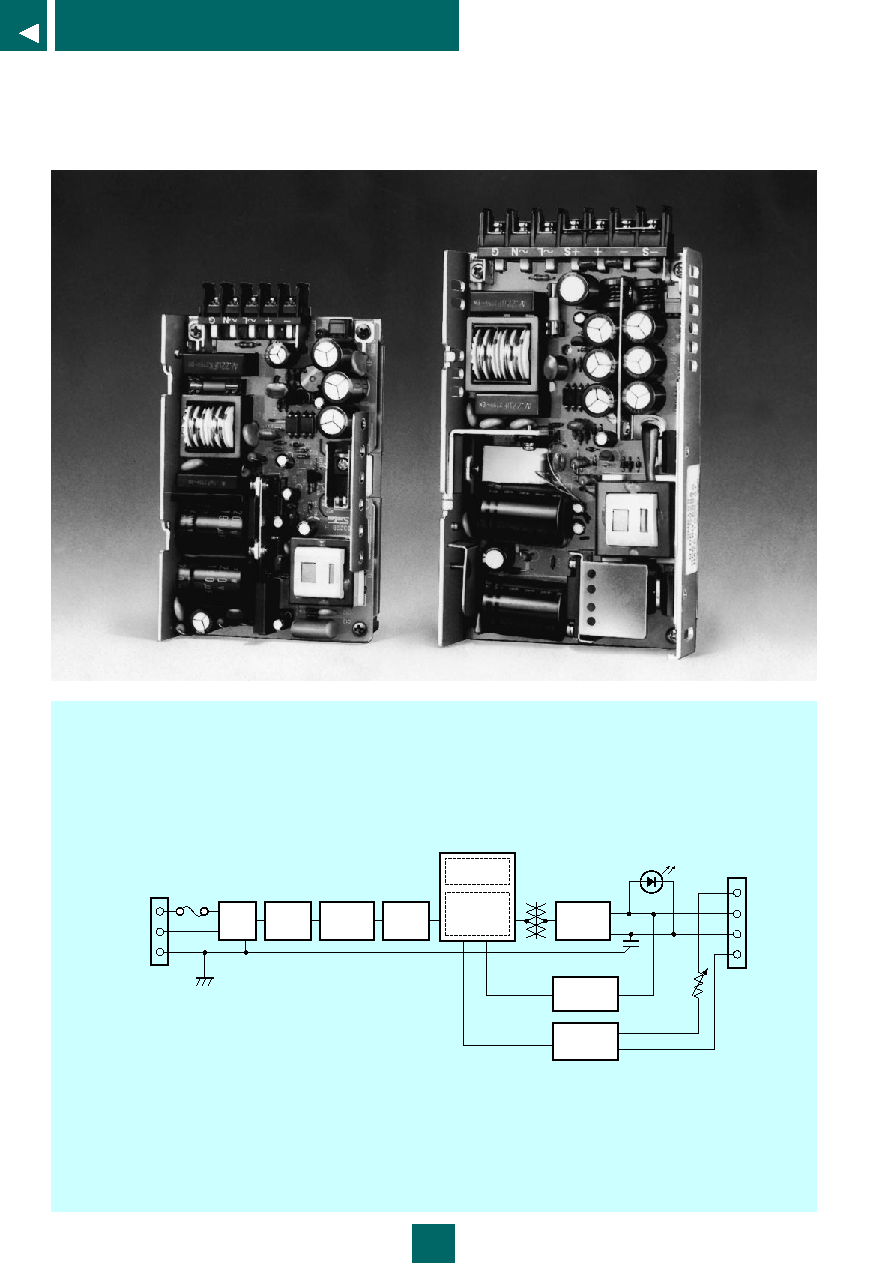
SWB Series 50W/100W
SWB Series
SWB Series
SINGLE OUTPUT
Open Frame with Optional Cover
Designed to meet UL, CSA, and TUV safety standards
50W, 100W
The SWB Series features Sanken' s proprietary resonant-mode power hybrid
IC and transformer. These models provide the high efficiency and low noise
that can only be realized with a resonant-mode supply. These supplies can
accept an input voltage range of 85 to 264 V, and feature continuous input
operation which requires no manual voltage selection. Their design makes it
easy to meet the power supply needs of world-wide applications.
FEATURES
· 80 to 87% efficiency (SWB Series 50 W),
81 to 88% efficiency (SWB Series 100 W)
· Low noise
· Small and lightweight, occupying only about 2/3 the volume of Sanken' s
equivalent FCC power supplies
20
SWB Series 50W/100W
Output
+S
+
S
AC 1(L)
AC 2(N)
FG
INPUT
Line
filter
Rectifier
Inrush
current
limiter
Switching
Control
Overcurrent
detection
Rectifier
and
filter
Operation indicator LED
Overvoltage
detection
Output
voltage
detection
V.ADJ
Automatic
input
switching
* +S and + are connected with a short bar, as are -S and -.
+S and -S are provided on 100 W model.
SWB Series circuit diagram
100W
SWB 100-05 SWB 100-12 SWB 100-24
2.7A/2.3A/1.4A/1.2A (typ)
30 A/60 A (max) (see Note 1)
81%
85%
88%
+5V
+12V
+24V
Rated voltage ±10%
20A
8.5A
4.5A
0 to 100%
100W
102W
108W
80
100
100
±3%
16ms (min)
370ms/260ms (typ)
0.3mA/0.6mA
SMZ, approx. 70 kHz
Provided
Not provided
Red LED operation indicator
0 to 60°C (derating above 50°C)
-25 to +85°C
30 to 90% (no condensation)
30 to 90% (no condensation)
2000 V AC for 1 minute
500 V AC for 1 minute
150 x 93 x 33 (W x D x H) (without cover)
about 450 g (without cover)
21
SWB Series 50W/100W
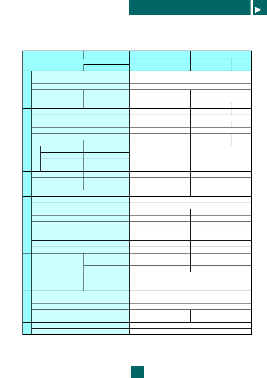
Rating
Item
Conditions
Rated Input Voltage
Input Voltage Range
Frequency Range
Input Current
Rated input/output conditions
Inrush Current
Rated input/output conditions
Efficiency (typ)
Rated input/output conditions
Rated Output Voltage
Adjustable Output Voltage Range
Rated Output Current
Adjustable Output Current Range
Maximum Output Power
Ripple Noise (mVp-p)
(see Note 2)
Rated input/output conditions
Static Input Range
85 to 132V AC
Static Load Range
0 to 100%
Time Driftt
10min. to 8 hours
Ambient Temperature Range 0 to +60°C
Output Holdup Time
Rated input/output conditions
Startup Time
Rated input/output conditions
Leakage Current
Rated input/output conditions
Switching Method, Transformer Frequency
Over Current Protection
Over Voltage Protection
Remote Sensing
Remote On/Off Control
Display
Operating Temperature
Storage Temperature
Operating Humidity
Storage Humidity
Insulation Withstand Voltage
Between Input and Output
(at normal temperature and
Between Input and Frame
humidity)
Between Output and Frame
Insulation Resistance
Between Input and Output
(at normal temperature and
Between Input and Frame
humidity)
Between Output and Frame
Vibration Resistance
Cooling Requirements
External Appearance
Size (dimensions in mm)
Weight
Safety Standards
EMI Standards
Input
Note 1: At cold start. (More current may flow at restart.)
Note 2: Ripple noise is measured with a 100 MHz oscilloscope, using a 1:1 probe.
Note 3: Output characteristics are measured at the output connector. Ripple noise is measured at a point 5 cm from the output connector, with a 63 V 47 µF
electrolytic capacitor attached at that point.
* "Rated input/output conditions" means that the switching power supply is operated under the rated input voltage, rated output voltage, rated output
current, rated frequency, and at an ambient temperature of 25°C and 60% humidity.
Output
(see Note 3)
Constant Voltage
Accuracy
Other
Additional Functions
Environmental
Insulation
Structural
Specifications
Applicable Standards
50W
SWB 050-05 SWB 050-12 SWB 050-24
1.2A/0.9A/0.8A/0.7A (typ)
30 A/60 A (max) (see Note 1)
80%
84%
87%
+5V
+12V
+24V
Rated voltage ±10%
10A
4.2A
2.1A
0 to 100%
50W
50.4W
50.4W
80
100
100
±3%
16ms (min)
360ms/250ms (typ)
0.3mA/0.6mA
SMZ, approx. 70 kHz
Not provided
Not provided
Red LED operation indicator
0 to 60°C (derating above 50°C)
-25 to +85°C
30 to 90% (no condensation)
30 to 90% (no condensation)
2000 V AC for 1 minute
500 V AC for 1 minute
125 x 80 x 29 (W x D x H) (without cover)
about 280 g (without cover)
100 M
(measured with 500 V DC Megger)
10 to 55 Hz, 2 G, 1 hour(in X, Y, and Z directions, with 3-minute vibration time)
Natural air cooling
Open frame (with optional cover)
Designed to meet UL 1950, CSA C22.2 No. 234 Level 3, TUV (EN 60950) (120/230 V AC)
Designed to meet FCC Class B (120 V AC), VDE 0871 Class A (230 V AC)
100V AC/120V AC/200V AC/230V AC
85 to 132 V AC, 170 to 264 V AC (automatic switching)
47 to 440 Hz (rated frequency is 50/60 Hz)
Detection above 105% of rated current (output cutoff)
Detection above 115% of rated voltage (output cutoff)
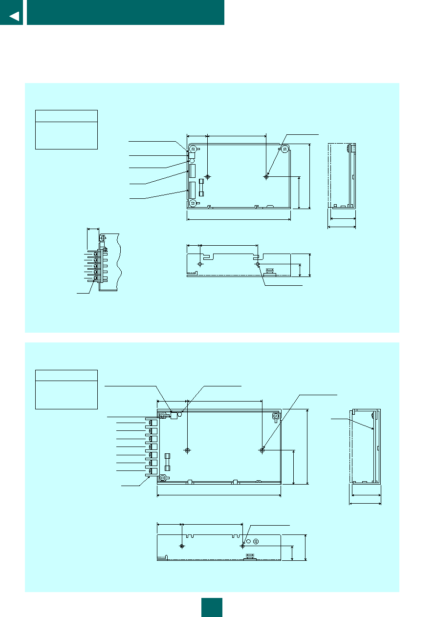
22
SWB Series 50W/100W
V
+V
AC (L)
AC (N)
FG
M3
(13)
CN2
CN1
25
70
±
0.3
125
±
1
29
±
1
32
±
1
70
±
0.3
15
3
9
8
0
±
1
4
1
5
1
1
5
2
7
.
5
Output voltage
adjustment knob
Adjustment knob
adjustment direction
LED operation
indicator
(with cover)
Terminal base
Component mounting
area
2-M3BR
Mounting hole
2-M3BR Mounting hole
50 W
(weight: approx. 280 g)
Model
SWB050-05
SWB050-12
SWB050-24
* Installation screws must be shorter than 5 mm.
30
33
±
1.0
36
±
1.0
37
90
±
0.3
1
8
.
5
3
2
.
2
9
3
±
1
.
0
4
2
75
±
0.3
150
±
1.0
PKG1
S
+
+S
AC (L)
AC (N)
FG
TB1
Output voltage
adjustment knob
Adjustment knob
adjustment direction
LED operation
indicator
(with cover)
Component mounting
area
2-M3BR
Mounting hole
2-M3BR
Mounting hole
100 W
(weight: approx. 450 g)
Model
SWB100-05
SWB100-12
SWB100-24
* Installation screws must be shorter than 5 mm.
23
SWB Series 50W/100W
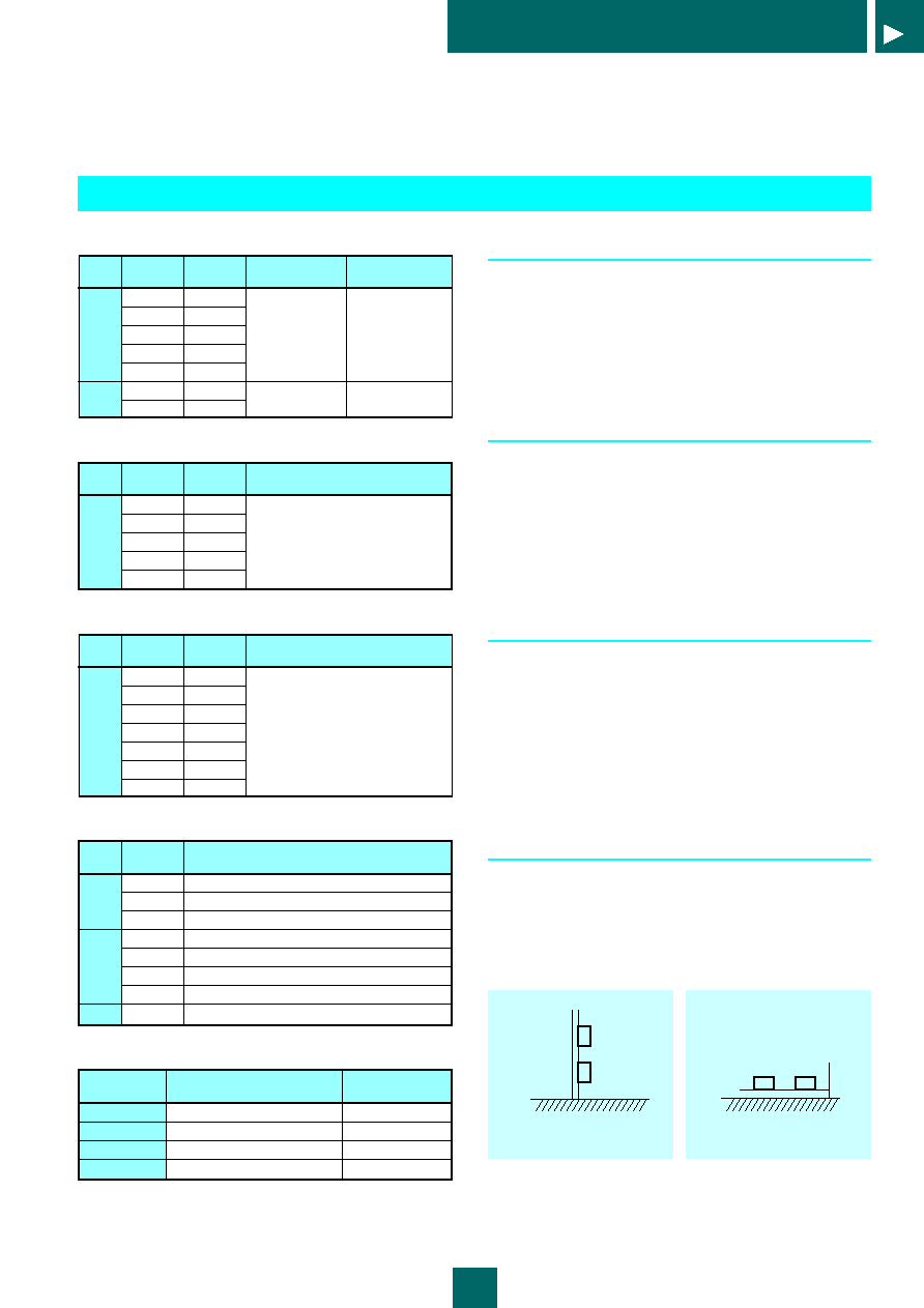
SWB050 Connector type
CN1
CN2
Pin
number
1
2
3
4
5
1 - 2
3 - 4
Terminal
name
FG
NC
AC (N)
NC
AC (L)
+
Corresponding
connector
VHR-5N (JST)
VHR-4N (JST)
Corresponding
contact
SVH-21T-P1.1 (JST)
SVH-21T-P1.1 (JST)
SWB100 Terminal base
(for terminal base types only)
SWB050 Terminal base type
TB1
Terminal
label
+
~L
~N
G
Terminal
name
+
AC (L)
AC (N)
FG
Corresponding crimp terminal
V1.25-3 (JST) or equivalent
TB1
Terminal
label
S
+
+S
~L
~N
G
Terminal
name
S
+
+S
AC (L)
AC (N)
FG
Corresponding crimp terminal
V2-4 (JST) or equivalent
Terminal names and functions
Input
Output
Terminal
name
AC (L)
AC (N)
FG
+
+S
S
NC
Function
AC input terminal. Includes an input fuse.
AC input terminal.
Frame ground (ground terminal).
DC output terminal, + side.
DC output terminal, - side.
Remote sensing terminal, + side.
(100 W model only)
Remote sensing terminal, - side.
(100 W model only)
No connect.
Options
Model number
option code
none
-CN
-C
-CN -C
Terminal name
Terminal base type, no cover
Connector type, no cover
Terminal base type, with cover
Connector type, with cover
Applicable models
all models
SWB050
all models
SWB050
Operating instruction (SWB Series)
1 Setting the output current
Output current may be adjusted using the adjustment knob
found near the connector or terminal base. Turning the knob
clockwise increases output current, while turning it
counterclockwise decreases output current. Use the power
supply with the output within its adjustable range and with a
load such that the supply's rated output power is not
exceeded.
2 Overcurrent protection
When the output is overloaded, the power supply's built-in
overcurrent protection will shut off the output. The
overcurrent protection is set to function when the output
current exceeds 105% of the rated current value (about 130%
of a standard output value).
To reset the overcurrent protection, remove the source of the
overload, turn off the power, and wait about a minute before
turning the power on again.
3 Overvoltage protection
If the output voltage increases for some reason, the
overvoltage condition is detected and the output shut off.
Once the overvoltage protection is activated, the output will
remain cut off as long as the input supply is energized. To
reset the overvoltage protection, turn off the power and wait
about a minute before turning the power on again.
Take care when applying power again, as there may still be a
problem with the output voltage (if there is, the overvoltage
protection will shut down the output again).
4 Mounting
To use the power supply with natural air cooling, mount the
supply so that both sides and the top are open, and so that
there is sufficient air current.
The power supply may be mounted either vertically or
horizontally, as shown below. Use mounting screws that are
5 mm long or less.
( A ) V e r t i c a l m o u n t i n g
( B ) H o r i z o n t a l m o u n t i n g