 | –≠–ª–µ–∫—Ç—Ä–æ–Ω–Ω—ã–π –∫–æ–º–ø–æ–Ω–µ–Ω—Ç: SWSWA | –°–∫–∞—á–∞—Ç—å:  PDF PDF  ZIP ZIP |

25
SWA Series 15W/30W/50W/100W/150W
Wide input voltage range with automatic voltage selection.
SW
SW
A Series
A Series
15W, 30W, 50W, 100W, 150W
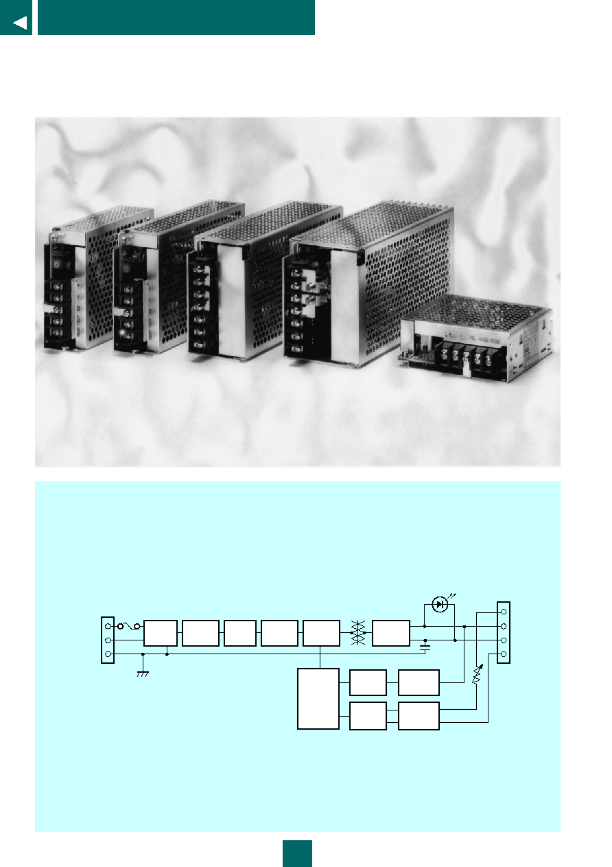
The SWA series is made up of general-purpose, single-output power supply
units for world-wide use. Input voltages from 85 to 264 V may be used with
no manual voltage selection required. The series has five advanced-design
models ranging from 15 to 150 W. The 100 W and 150 W models are
equipped with Power Factor Correction circuits, and take into account the
IEC 555 Part 2 regulations on harmonic currents.
FEATURES
∑ Wide input voltage range
∑ High power factor of 0.95 achieved using a Power Factor Correction IC
(100 W, 150 W)
∑ New Barrierless Transformer technology for reduced size
∑ MOSFET-based main switching circuit for high efficiency
∑ Designed to meet UL, CSA, and VDE safety standards
∑ The 100 W and 150 W models are equipped with Power Factor Correction
circuits.
26
SWA Series 15W/30W/50W/100W/150W
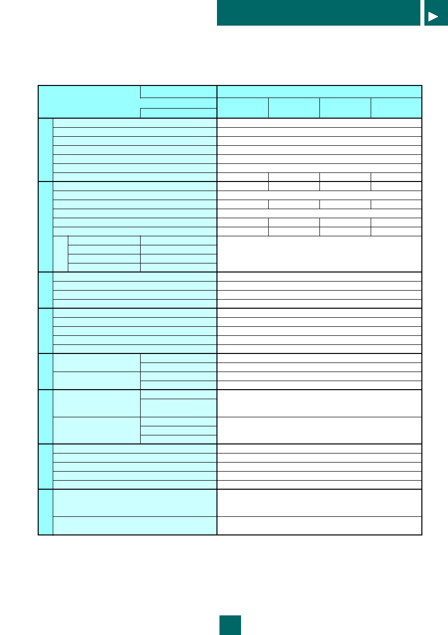
Line
filter
Inrush
current
limiter
Switching
Overcurrent
Detector
Overvoltage
Detector
Output
Voltage
Detector
Photo
Coppler
Photo
Coppler
Rectifier
Filter
PFC
Rectifier
and
filter
LED Indicator
Output
+S
+
≠
≠S
V.ADJ
AC 1(L)
AC 2(N)
FG
INPUT
* No power correction on 15 to 50 W models.
+S and + are connected with a short bar, as are -S and -.
SWA Series circuit diagram
27
SWA Series 15W/30W/50W/100W/150W
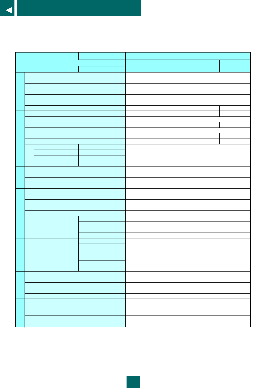
Rating
Item
Conditions
Rated Input Voltage
Input Voltage Range
Rated Frequency
Frequency Range
Input Current
(see Note 1)
Inrush Current
(see Note 1, 2)
Efficiency (typ)
(see Note 1)
Rated Output Voltage
Adjustable Output Voltage Range
Rated Output Current
Adjustable Output Current Range
Maximum Output Power
Ripple (mVp-p)
(see Note 1, 4)
Static Input Range
85 to 264V AC
Static Load Range
0 to 100%
Time Driftt
10min. to 8 hours
Ambient Temperature Range 0 to +50∞C
Output Holdup Time
(see Note 1)
Startup Time
(see Note 1)
Leakage Current
(see Note 1)
Switching Method, Transformer Frequency
Over Current Protection
Over Voltage Protection
Remote Sensing
Remote On/Off Control
Display
Temperature
Operating Temperature
Storage Temperature
Relative Humidity
Operating Humidity
Storage Humidity
Insulation Withstand Voltage
Between Input and Output
(see Note 5)
Between Input and Frame
Between Output and Frame
Insulation Resistance
Between Input and Output
Between Input and Frame
Between Output and Frame
Vibration Resistance
Cooling Requirements
External Appearance
Size (dimensions in mm)
Weight
Safety Standards
EMI Standards
Input
Note 1: Rated input/output conditions means that the switching power supply is operated under the rated input voltage, rated frequency, rated output voltage, rated output current, and
at an ambient temperature of 25∞C and 60% humidity.
Note 2: At cold start. (More current may flow at restart.)
Note 3: All output characteristics are measured at a point 5 cm from the output connector, with a 63 V 47 µF electrolytic capacitor attached at that point.
Note 4: Ripple noise is measured with a 100 MHz oscilloscope, using a 1:1 probe.
Note 5: At room temperature and normal humidity.
Output
(see Note 3)
Other
Additional Functions
Environmental
Insulation
Structural
Specifications
Applicable Standards
15W
SWA 015-05
SWA 015-12
SWA 015-15
SWA 015-24
100-240V AC
85 to 264V AC
50/60 Hz
47 to 440 Hz
0.4/0.23A (typ)
25/50 A (max)
72%
75%
75%
77%
+5V
+12V
+15V
+24V
Rated voltage ±10%
3.0A
1.3A
1.07A
0.7A
0 to 100%
15W
15.6W
15W
16.8W
120mVp-p
180mVp-p
180mVp-p
240mVp-p
±3%
10ms (min)
20ms (typ)
0.5mA (max)
RCC topology, approx. 70 kHz (under rated input/output conditions)
Detection above 105% of rated current (output cutoff)
Detection above 115% to 145% of rated voltage (output cutoff)
Not provided
Not provided
LED operation indicator
0 to 50∞C (no cover)
-25 to +85∞C
30 to 90% (no condensation)
30 to 90% (no condensation)
2000 V AC for 1 minute, 2400 V AC for 1 second (Leakage current of 15 mA or less)
500 V AC for 1 minute, 600 V AC for 1 second (Leakage current of 15 mA or less)
100 M
(measured with 500 V DC Megger)
10 to 55 Hz, 2 G, 1 hour (in X, Y, and Z directions)
Natural air cooling
Open frame (with optional cover)
35 x 99 x 97 (W x D x H) (without cover)
265 g (open frame)
Designed to meet UL 1950
Designed to meet CSA C22.2 No. 234
Designed to meet EN 60950
Designed to meet VDE 0871 Class A (200 to 240 V AC)
Designed to meet FCC Class B (100 to 120 V AC)
Constant Voltage
Accuracy
28
SWA Series 15W/30W/50W/100W/150W
Rating
Item
Conditions
Rated Input Voltage
Input Voltage Range
Rated Frequency
Frequency Range
Input Current
(see Note 1)
Inrush Current
(see Note 1, 2)
Efficiency (typ)
(see Note 1)
Rated Output Voltage
Adjustable Output Voltage Range
Rated Output Current
Adjustable Output Current Range
Maximum Output Power
Ripple (mVp-p)
(see Note 1, 4)
Static Input Range
85 to 264V AC
Static Load Range
0 to 100%
Time Driftt
10min. to 8 hours
Ambient Temperature Range 0 to +50∞C
Output Holdup Time
(see Note 1)
Startup Time
(see Note 1)
Leakage Current
(see Note 1)
Switching Method, Transformer Frequency
Over Current Protection
Over Voltage Protection
Remote Sensing
Remote On/Off Control
Display
Temperature
Operating Temperature
Storage Temperature
Relative Humidity
Operating Humidity
Storage Humidity
Insulation Withstand Voltage
Between Input and Output
(see Note 5)
Between Input and Frame
Between Output and Frame
Insulation Resistance
Between Input and Output
Between Input and Frame
Between Output and Frame
Vibration Resistance
Cooling Requirements
External Appearance
Size (dimensions in mm)
Weight
Safety Standards
EMI Standards
Input
Note 1: Rated input/output conditions means that the switching power supply is operated under the rated input voltage, rated frequency, rated output voltage, rated output current, and
at an ambient temperature of 25∞C and 60% humidity.
Note 2: At cold start. (More current may flow at restart.)
Note 3: All output characteristics are measured at a point 5 cm from the output connector, with a 63 V 47 µF electrolytic capacitor attached at that point.
Note 4: Ripple noise is measured with a 100 MHz oscilloscope, using a 1:1 probe.
Note 5: At room temperature and normal humidity.
Output
(see Note 3)
Other
Additional Functions
Environmental
Insulation
Structural
Specifications
Applicable Standards
Constant Voltage
Accuracy
30W
SWA 030-05
SWA 030-12
SWA 030-15
SWA 030-24
100-240V AC
85 to 264V AC
50/60 Hz
47 to 440 Hz
0.7/0.46A (typ)
25/50 A (max)
72%
75%
75%
77%
+5V
+12V
+15V
+24V
Rated voltage ±10%
6.0A
2.5A
2.0A
1.3A
0 to 100%
30W
30W
30W
31.2W
120mVp-p
180mVp-p
180mVp-p
240mVp-p
±3%
10ms (min)
20ms (typ)
0.5mA (max) (V
in
=100V
AC
)/0.75mA (V
in
=240V
AC
)
RCC topology, approx. 70 kHz (under rated input/output conditions)
Detection above 105% of rated current (output cutoff)
Over Voltage Protection Detection above approx. 115 to 145% of rated voltage
Not provided
Not provided
LED operation indicator
0 to 50∞C (no cover)
-25 to +85∞C
30 to 90% (no condensation)
30 to 90% (no condensation)
2000 V AC for 1 minute, 2400 V AC for 1 second (Leakage current of 15 mA or less)
500 V AC for 1 minute, 600 V AC for 1 second (Leakage current of 15 mA or less)
100 M
(measured with 500 V DC Megger)
10 to 55 Hz, 2 G, 1 hour (in X, Y, and Z directions)
Natural air cooling
Open frame (with optional cover)
35 x 116 x 97 (W x D x H) (without cover)
320 g (open frame)
Designed to meet UL 1950
Designed to meet CSA C22.2 No. 234
Designed to meet EN 60950
Designed to meet VDE 0871 Class A (200 to 240 V AC)
Designed to meet FCC Class B (100 to 120 V AC)
29
SWA Series 15W/30W/50W/100W/150W
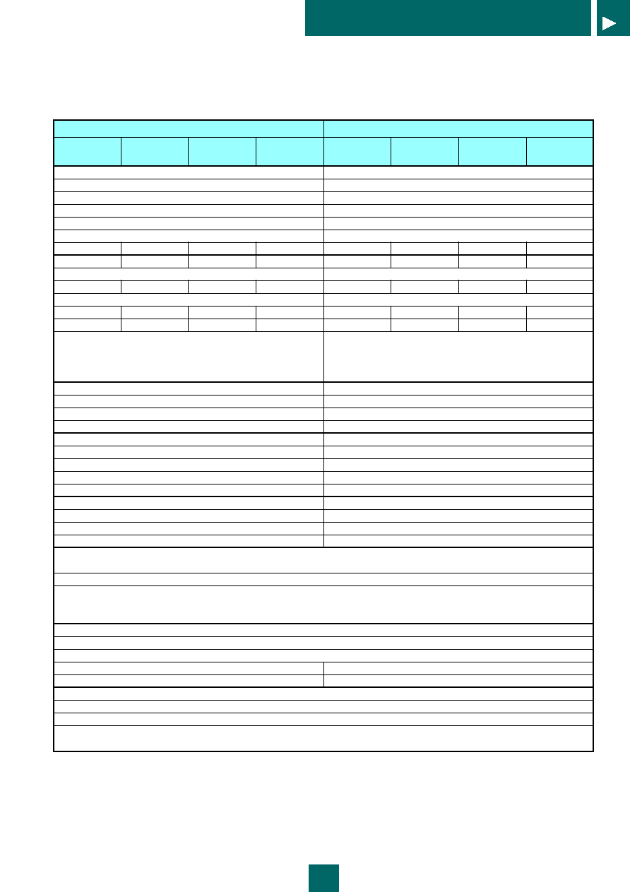
50W
SWA 050-05
SWA 050-12
SWA 050-15
SWA 050-24
100-240V AC
85 to 264V AC
50/60 Hz
47 to 440 Hz
1.2/0.7A (typ)
25/50 A (max)
72%
75%
75%
77%
+5V
+12V
+15V
+24V
Rated voltage ±10%
10.0A
4.2A
3.4A
2.1A
0 to 100%
50.0W
50.4W
51.0W
50.4W
120mVp-p
180mVp-p
180mVp-p
240mVp-p
±3%
10ms (min)
20ms (typ)
0.5mA (max) (V
in
=100V
AC
)/0.75mA (V
in
=240V
AC
)
RCC topology, approx. 70 kHz (under rated input/output conditions)
Detection above 105% of rated current (output cutoff)
Over Voltage Protection Detection above approx. 115 to 145% of rated voltage
Not provided
Not provided
LED operation indicator
0 to 50∞C (no cover)
-25 to +85∞C
30 to 90% (no condensation)
30 to 90% (no condensation)
37 x 159 x 97 (W x D x H) (without cover)
380 g (open frame)
2000 V AC for 1 minute, 2400 V AC for 1 second (Leakage current of 15 mA or less)
500 V AC for 1 minute, 600 V AC for 1 second (Leakage current of 15 mA or less)
100 M
(measured with 500 V DC Megger)
10 to 55 Hz, 2 G, 1 hour (in X, Y, and Z directions)
Natural air cooling
Open frame (with optional cover)
Designed to meet UL 1950
Designed to meet CSA C22.2 No. 234
Designed to meet EN 60950
Designed to meet VDE 0871 Class A (200 to 240 V AC)
Designed to meet FCC Class B (100 to 120 V AC)
100W
SWA 100-05
SWA 100-12
SWA 100-15
SWA 100-24
100-240V AC
85 to 264V AC
50/60 Hz
47 to 440 Hz
1.6/0.7A (typ)
20/40 A (max)
77%
78%
80%
80%
+5V
+12V
+15V
+24V
Rated voltage ±10%
20.0A
8.5A
7.0A
4.5A
0 to 100%
100.0W
102.0W
105.0W
108.0W
120mVp-p
180mVp-p
180mVp-p
240mVp-p
±3%
20ms (min)
1000/500 ms (typ)
0.5mA (max) (V
in
=100V
AC
)/0.75mA (V
in
=240V
AC
)
FCC topology, approx. 150 kHz (under rated input/output conditions)
Detection above 120% of rated current (output cutoff)
Over Voltage Protection Detection above approx. 115 to 145% of rated voltage
Provided
Not provided
LED operation indicator
0 to 50∞C (no cover)
-25 to +85∞C
30 to 90% (no condensation)
30 to 90% (no condensation)
50 x 180 x 93 (W x D x H) (without cover)
700 g (open frame)