Capable of driving loads to 4 A at supply voltages to 60 V (induc-
tive loads to 35 V), the UDN2944W is a quad high-current, high-
voltage source driver. Each of the four power drivers can provide
space- and cost-saving interface between low-level signal-processing
circuits and high-power loads in harsh environments.
Individual supply lines have been provided for each pair of drivers
so that different supplies can be used to drive multiple loads. The
controlling inputs are TTL or CMOS compatible. The outputs include
transient-suppression diodes for inductive loads.
This quad Darlington array is designed to serve as an interface
between low-level circuitry and peripheral-power loads such as sole-
noids, motors, incandescent displays, heaters, and similar loads of up to
240 W per channel. The UDN2944W is an ideal complement to the
UDN2878W quad 4 A sink driver.
For maximum power-handling capability, the UDN2944W driver
is supplied in a 12-pin single in-line, power-tab package that allows
efficient attachment of an external heat sink for maximum allowable
package power dissipation. An external heat sink is usually required
for proper operation of this device. The tab is at ground potential and
needs no insulation.
FEATURES
I Output Current to 4 A
I Output Voltage to 60 V
I Loads to 960 W
I Integral Output Suppression Diodes
I TTL and CMOS Compatible Inputs
I Plastic Single In-Line Package
I Heat-Sink Tab
2944
QUAD HIGH-CURRENT,
HIGH-VOLTAGE SOURCE DRIVER
ABSOLUTE MAXIMUM RATINGS
at +25
∞
C Free-Air Temperature
Supply Voltage Range, V
S
..... 10 V to 60 V
Output Current, I
OUT
(continuous) ............................... - 4.0 A
(peak) ......................................... - 5.0 A
Input Voltage, V
IN
................................ 15 V
Package Power Dissipation,
P
D
....................................... See Graph
Operating Temperature Range,
T
A
................................ -20
∞
C to +85
∞
C
Storage Temperature Range,
T
S
.............................. -55
∞
C to +150
∞
C
Output current rating will be limited by
ambient temperature, duty cycle, heat
sinking, air flow, and number of outputs
conducting. Under any set of conditions, do
not exceed the -5.0 A peak current or a
junction temperature of +150
∞C.
Dwg. No. A-13,054
Always order by complete part number:
UDN2944W .
V
S
Data Sheet
29309.10
2944
QUAD HIGH-CURRENT,
HIGH-VOLTAGE
SOURCE DRIVER
115 Northeast Cutoff, Box 15036
Worcester, Massachusetts 01615-0036 (508) 853-5000
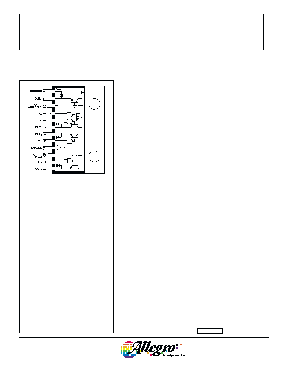
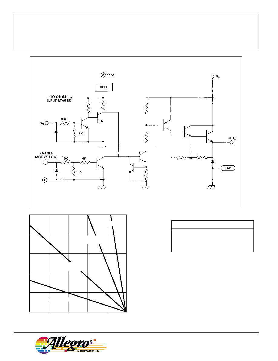
PARTIAL SCHEMATIC
50
75
100
125
150
10
6
4
2
0
ALLOWABLE PACKAGE POWER DISSIPATION IN WATTS
TEMPERATURE IN
∞C
8
25
R = 2.0
∞C/W
JT
Dwg. GP-012B
FREE AIR, R = 38
∞C/W
JA
3.0
∞C/W HEAT SINK
R = 5.0
∞C/W
JA
12
∞C/W HEAT SINK
R = 14
∞C/W
JA
W
Copyright © 1986, 2000 Allegro MicroSystems, Inc.
TRUTH TABLE
INPUT
ENABLE
OUTPUT
L
L
L
H
L
H
L
H
L
H
H
L
NOTE: Pin 3 must be connected to V
S
for
operation of input logic gates.
Dwg. No. A-13,058
2944
QUAD HIGH-CURRENT,
HIGH-VOLTAGE
SOURCE DRIVER
www.allegromicro.com
ELECTRICAL CHARACTERISTICS at T
A
= +25
∞
C, T
J
+150
∞
C, V
S
= 60 V, V
ENABLE
= 0 V
(unless otherwise noted).
Limits
Characteristic
Symbol
Test Conditions
Min.
Max.
Units
Supply Voltage Range
V
S
10
60
V
Output Leakage Current
I
CEX
V
OUT
= 0 V, V
ENABLE
= 2.4 V
--
50
µA
Output Sustaining Voltage
V
CE(sus)
I
OUT
= -4 A, L = 3 mH
35
--
V
Output Saturation Voltage
V
CE(SAT)
I
OUT
= -1 A, V
IN
= 2.4 V
--
1.8
V
I
OUT
= -4 A, V
IN
= 2.4 V
--
2.5
V
Input Voltage
Logic 1
V
IN(1)
or V
ENABLE(1)
2.0
--
V
Logic 0
V
IN(0)
or V
ENABLE(0)
--
0.8
V
Input Current
Logic 1
V
IN(1)
or V
ENABLE(1)
= 2.4 V
--
220
µA
V
IN(1)
or V
ENABLE(1)
= 12 V
--
1.5
mA
Logic 0
V
IN(0)
or V
ENABLE(0)
= 0.8 V
--
50
µA
Total Supply Current
I
S
All drivers on, All outputs open
--
25
mA
Clamp Diode Leakage Current
I
R
V
R
= 60 V
--
50
µA
Clamp Diode Forward Voltage
V
F
I
F
= 4 A
--
2.2
V
Turn-On Delay
t
ON
0.5 E
in
to 0.5 E
out
, R
L
= 15
--
2.0
µs
Turn-Off Delay
t
OFF
0.5 E
in
to 0.5 E
out
, R
L
= 15
--
10
µs
NOTE: Negative current is defined as coming out of (sourcing) the device being tested.
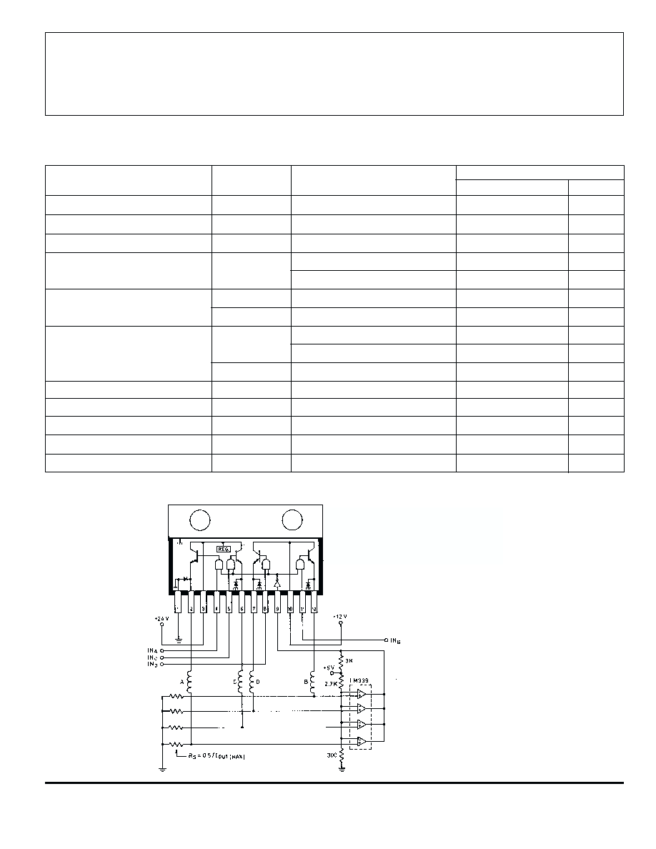
TYPICAL APPLICATION
QUAD RELAY DRIVE
(Using 2 Voltage Sources
and Optional PWM Current Limiting)
2944
QUAD HIGH-CURRENT,
HIGH-VOLTAGE
SOURCE DRIVER
115 Northeast Cutoff, Box 15036
Worcester, Massachusetts 01615-0036 (508) 853-5000
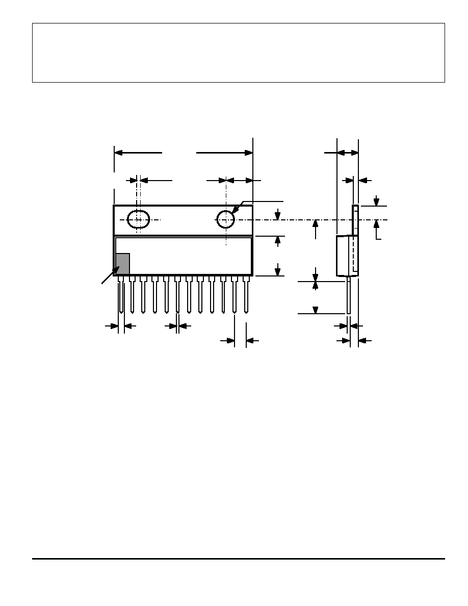
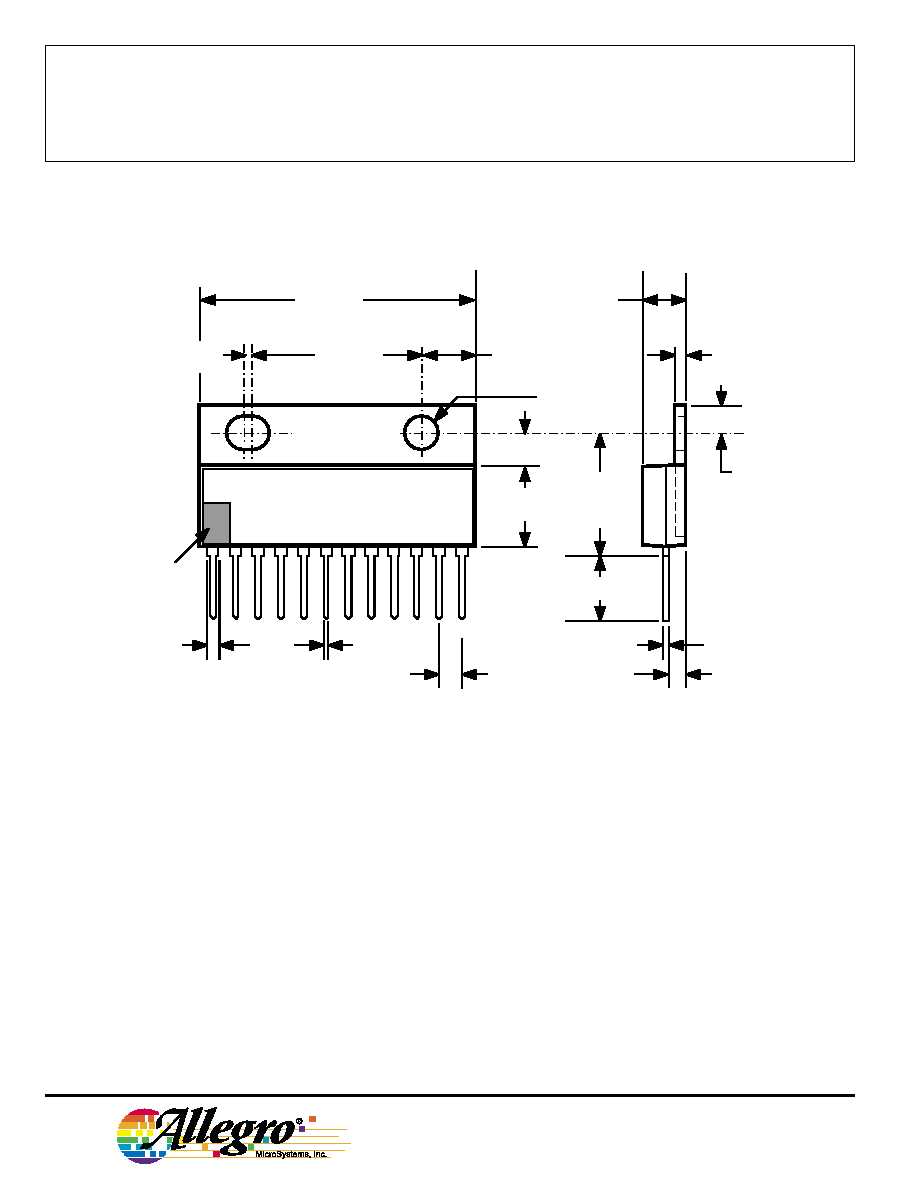
Dimensions in Inches
(controlling dimensions)
NOTES: 1. Lead thickness is measured at seating plane or below.
2. Lead spacing tolerance is non-cumulative.
3. Exact body and lead configuration at vendor's option within limits shown.
4. Lead gauge plane is 0.030" below seating plane.
5. Supplied in standard sticks/tubes of 15 devices.
Dwg. MP-007 in
1.260
1.240
0.775
0.765
0.020
0.155
0.145
¯
0.180
MAX
0.055
0.045
0.135
0.100
0.290
MIN
0.080
0.070
0.365
0.100
±0.010
0.030
0.020
0.065
0.035
1
0.023
0.018
0.140
0.570
0.540
0.245
0.225
12
INDEX
AREA