2943
HIGH-CURRENT HALF-BRIDGE MOTOR DRIVER
DISCONTINUED
PRODUCT
-- FOR REFERENCE
ONL
Y
Designed for use as a general-purpose motor driver, the
UDN2943Z half-bridge driver combines high-current sink and source
drivers with logic stages, level shifting, diode transient protection, and
a voltage regulator for single-supply operation. Capable of operating
in extremely harsh environments, this device can withstand high
ambient temperatures, output overloads, and repeated power supply
transient voltages without damage. The driver can be used in pairs for
full-bridge operation, or as triplets in three-phase brushless dc motor-
drive applications.
The input circuitry is compatible with TTL, low-voltage CMOS,
and NMOS logic. Logic lockout prevents both source and sink drivers
from turning ON simultaneously. Each driver is turned ON by an active-
low input, making the UDN2943Z especially desirable in many micro-
processor applications. An accidental input open circuit will turn OFF
the corresponding output. The device also provides an internally-
generated dead time to prevent crossover currents during output
switching. Monolithic, space-saving construction offers reliability
unobtainable with discrete components.
Saturated output drivers provide for low saturation voltage at the
maximum rated current. Internal short-circuit protection, activated at
load currents above 1 A, protects the source driver from accidental
short-circuits between the output and ground.
The UDN2943Z driver is rated for continuous operation with
inductive loads at supply voltages of up to 24 V. With supply voltage
transients (to 35 V maximum), a high-voltage protection circuit
becomes operative, shutting OFF both output drivers. The internal
thermal shutdown is triggered by a nominal junction temperature
of 160
�
C.
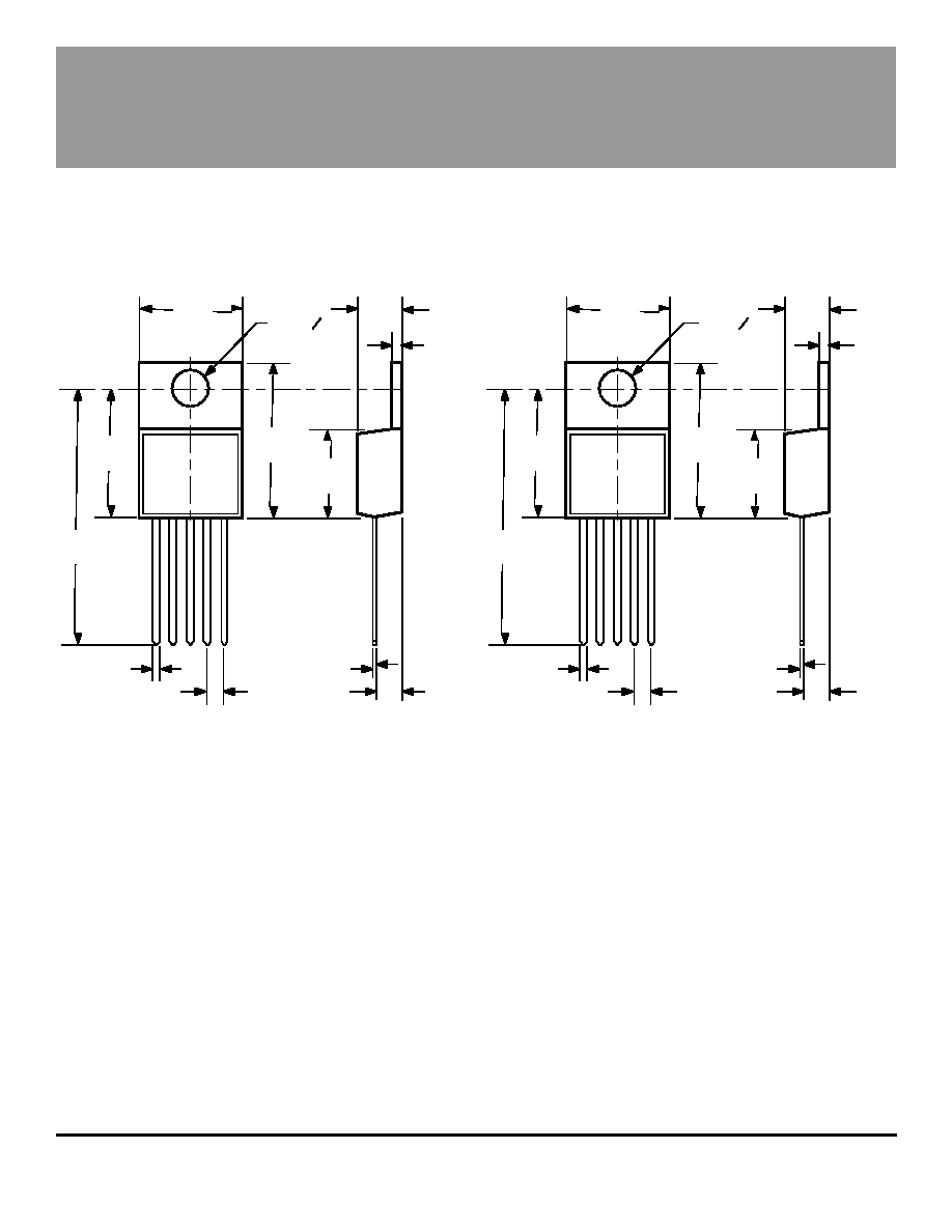
Single-chip construction and a 5-lead power-tab TS-001 plastic
package provide cost-effective and reliable systems designs.
It also features excellent power dissipation ratings, minimum size, and
ease of installation. The heat-sink tab is at ground potential and does
not require insulation.
FEATURES
s
�
1 A Output Current
s
8.5 V to 24 V Operating Range
s
Saturated Output Drivers
s
Crossover-Current Protected
s
Logic-Compatible Inputs
s
Withstands 35 V Supply Transients
s
Output-Transient Protection
s
Internal Over-Voltage Protection
s
Tri-State Output
s
Internal Short-Circuit Protection
HIGH-CURRENT
HALF-BRIDGE MOTOR DRIVER
2943
ABSOLUTE MAXIMUM RATINGS
Supply Voltage, Range V
S
.... 8.5 V to 35 V*
Output Voltage, V
CE(sus)
....................... 24 V
Input Voltage Range, V
IN
.... -0.3 V to +18 V
Continuous Output Current, I
OUT
......
�
1.0 A
Package Power Dissipation,
P
D
....................................... See Graph
Operating Temperature Range,
T
A
................................. -20
�
C to +85
�
C
Storage Temperature Range,
T
S
............................... -55
�
C to +150
�
C
*Internal high-voltage shutdown above 24 V.
Always order by complete part number: UDQ2943Z .
TM
MicroSystems, Inc.
TM
A
A
Data Sheet
29318.4B
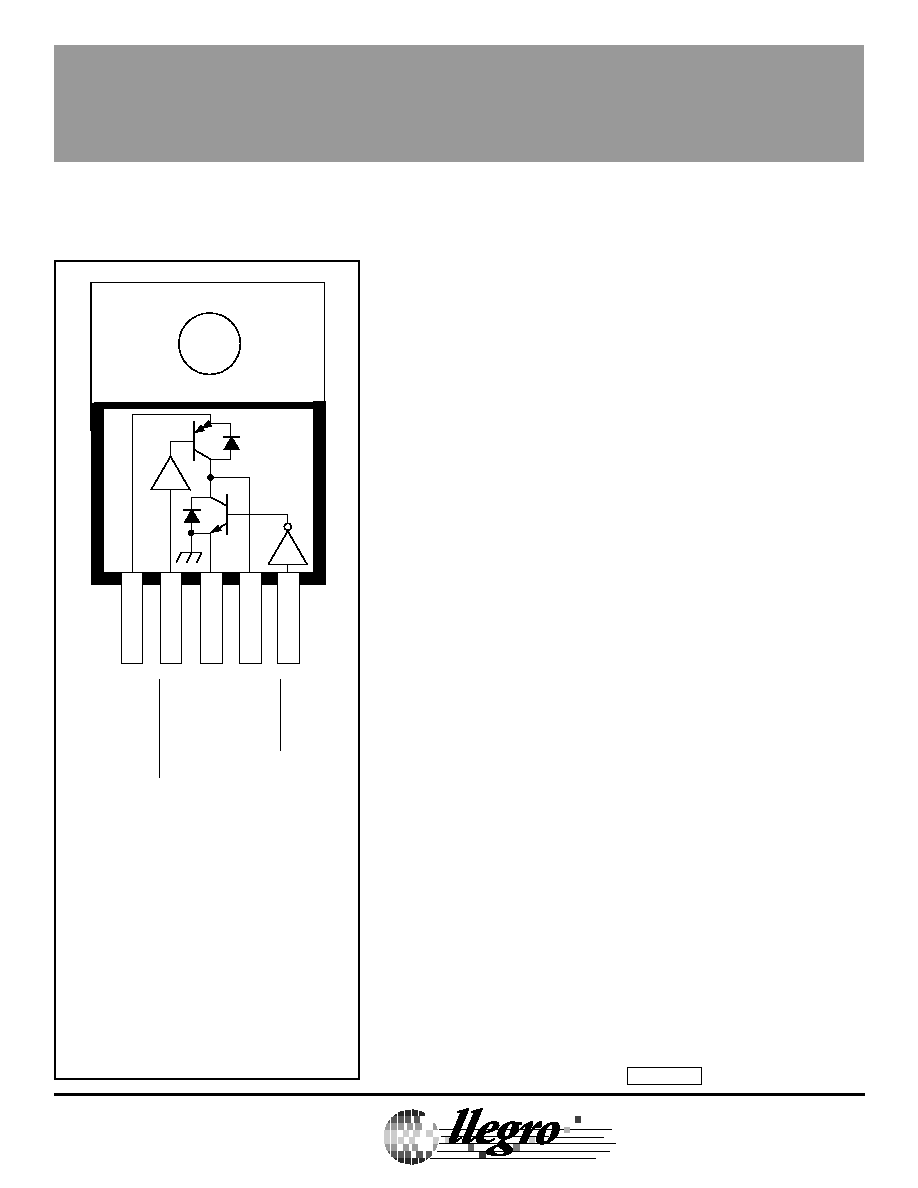
1
2
3
4
5
OUTPUT
SOURCE INPUT
GROUND
SINK INPUT
Dwg. PP-022-1
+V
S
2943
HIGH-CURRENT HALF-BRIDGE MOTOR DRIVER
TM
MicroSystems, Inc.
TM
A
A
115 Northeast Cutoff, Box 15036
Worcester, Massachusetts 01615-0036 (508) 853-5000
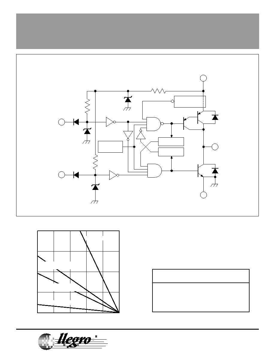
FUNCTIONAL BLOCK DIAGRAM
LOGIC TRUTH TABLE
Source Driver
Sink Driver
Output
Pin 2
Pin 5
Pin 4
Low
Low
High
Low
High
High
High
Low
Low
High
High
High Z
L-TO-H DELAY
H-TO-L DELAY
HIGH-CURRENT
SENSE
GROUND
3
SOURCE
INPUT
SINK
INPUT
V
S
OUTPUT
OVER-VOLT.
& TSD
2.1 V
2.1 V
6.35 V
Dwg. FP-038
2
5
1
4
115 Northeast Cutoff, Box 15036
Worcester, Massachusetts 01615-0036 (508) 853-5000
Copyright � 1986, 1994, Allegro MicroSystems, Inc.
50
75
100
125
150
15
10
5
0
ALLOWABLE PACKAGE POWER DISSIPATION IN WATTS
TEMPERATURE IN
�
C
20
25
Dwg. GP-014A
FREE AIR, R = 65
�
C/W
JA
AAVID 5071B + 5072B HEAT SINKS,
R = 9.0
�
C/W
JA
STAVER V1-5 HEAT SINK,
R = 13
�
C/W
JA
R = 3.0
�
C/W
JT
2943
HIGH-CURRENT HALF-BRIDGE MOTOR DRIVER
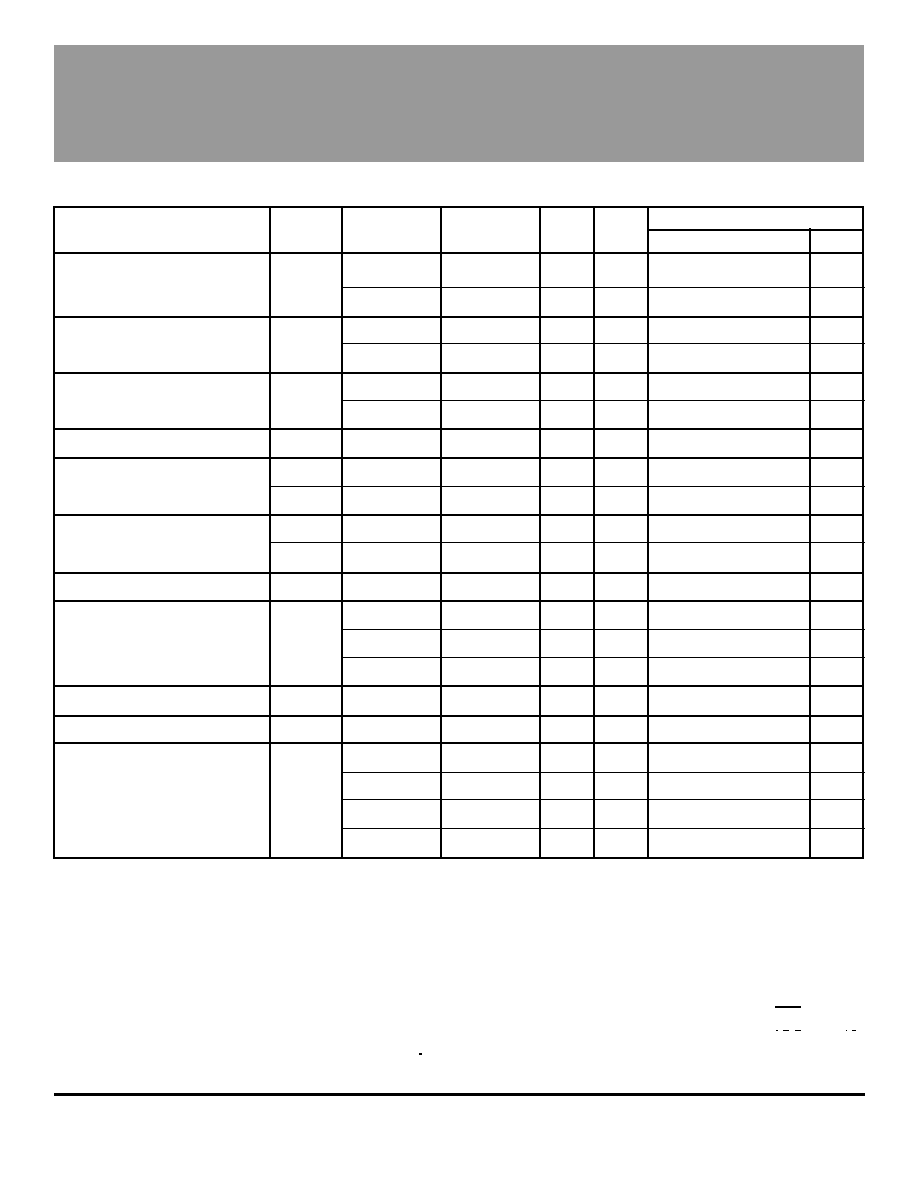
ELECTRICAL CHARACTERISTICS at T
A
= +25
�
C, V
S
= +24 V (unless otherwise noted).
Source Driver
Sink Driver
Output
Limits
Characteristic
Symbol
Input, Pin 2
Input, Pin 5
Pin 4
Other
Min.
Typ.
Max.
Units
Output Leakage Current
I
CEX
2.4 V
2.4 V
0 V
--
--
-10
-100
�
A
(V
S
= +35 V)
2.4 V
2.4 V
35 V
--
--
10
100
�
A
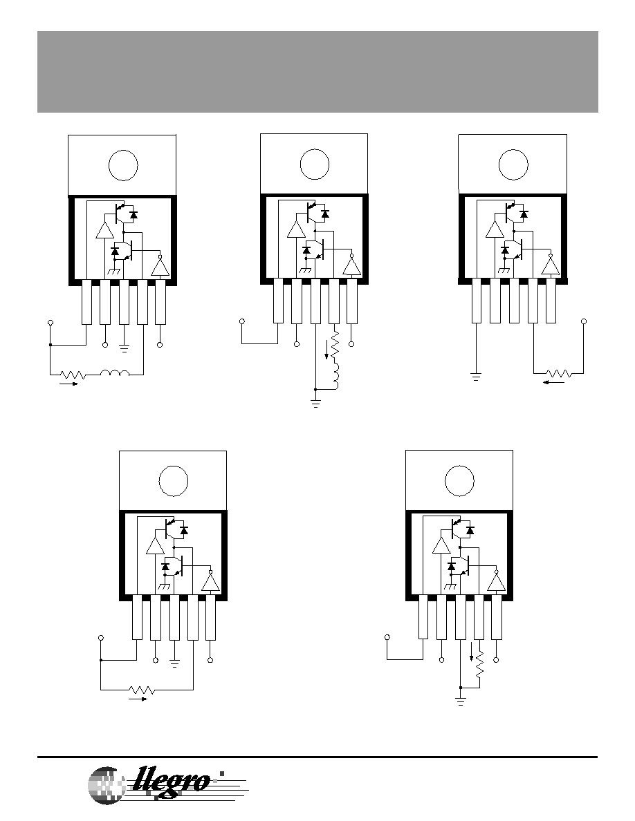
Output Sustaining Voltage
V
CE(sus)
2.4 V
0.8 to 2.4 V
1.0 A
Fig. 1A
24
--
--
V
0.8 to 2.4 V
2.4 V
-1.0 A
Fig. 1B
24
--
--
V
Output Saturation Voltage
V
CE(SAT)
0.8 V
2.4 V
-1.0 A
--
--
1.2
1.8
V
2.4 V
0.8 V
1.0 A
--
--
0.6
1.0
V
Short-Circuit Source Current
I
SC
0.8 V
2.4 V
0 V
--
1.0
--
1.8
A
Logic Input Voltage
V
IN(1)
--
--
--
--
2.0
--
--
V
V
IN(0)
--
--
--
--
--
--
0.8
V
Input Current
I
IN(1)
2.4 V
2.4 V
NC
--
--
10
100
�
A
I
IN(0)
0.8 V
0.8 V
NC
--
--
-50
-200
�
A
Clamp Diode Forward Voltage
V
F
NC
NC
1.0 A
Fig. 2
--
1.5
2.0
V
Logic Supply Current
I
S
2.4 V
2.4 V
NC
--
--
15
30
mA
2.4 V
0.8 V
NC
--
--
55
75
mA
0.8 V
2.4 V
NC
--
--
30
40
mA
Thermal Shutdown Temperature
T
J
--
--
--
--
--
160
--
�
C
Over-Voltage Shutdown
V
S
--
--
--
--
24
--
35
V
Propagation Delay
t
PD
2.4 V
2.4 V to 0.8 V
0.4 A
Fig. 3
--
0.6
--
�
s
0.8 to 2.4 V
2.4 V
-0.4 A
Fig. 4
--
1.0
--
�
s
2.4 V
0.8 to 2.4 V
0.4 A
Fig. 3
--
1.1
--
�
s
2.4 to 0.8 V
2.4 V
-0.4 A
Fig. 4
--
0.6
--
�
s
Notes: Negative current is defined as coming out of (sourcing) the specified device pin.
Typical Data is for design information only.
OUTPUT
CURRENT
SOURCE INPUT
VOLTAGE
SINK INPUT
Dwg. WP-024
VOLTAGE
+
0
�
SINKING CURRENT
SOURCING CURRENT
OPEN CIRCUIT
Dwg. WP-024