 | –≠–ª–µ–∫—Ç—Ä–æ–Ω–Ω—ã–π –∫–æ–º–ø–æ–Ω–µ–Ω—Ç: UGN3060KA | –°–∫–∞—á–∞—Ç—å:  PDF PDF  ZIP ZIP |
The UGS3059KA and UGN/UGS3060KA ac-coupled Hall-effect
gear-tooth sensors are monolithic integrated circuits that switch in
response to changing differential magnetic fields created by moving
ferrous targets. These devices are ideal for use in non-zero-speed,
gear-tooth-based speed, position, and timing applications such as in
anti-lock braking systems, transmissions, and crankshafts.
Both devices, when coupled with a back-biasing magnet, can be
configured to turn ON or OFF with the leading or trailing edge of a
gear-tooth or slot. Changes in fields on the magnet face caused by a
moving ferrous mass are sensed by two integrated Hall transducers
and are differentially amplified by on-chip electronics. This differential
sensing design provides immunity to radial vibration within the devices'
operating air gaps. Steady-state magnet and system offsets are
eliminated using an on-chip differential band-pass filter. This filter also
provides relative immunity to interference from RF and electromag-
netic sources. The on-chip temperature compensation and Schmitt
trigger circuitry minimizes shifts in effective working air gaps and
switch points over temperature, allowing operation to low frequencies
over a wide range of air gaps and temperatures.
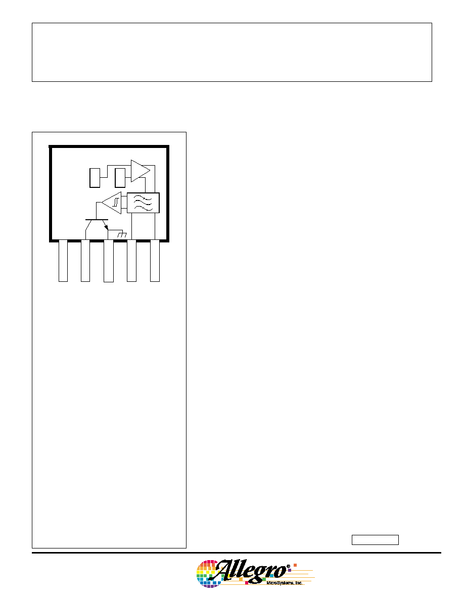
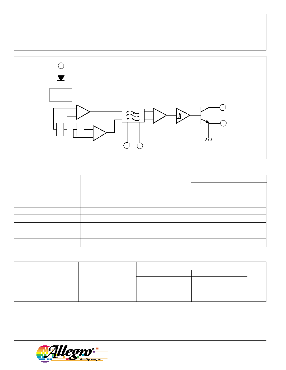
Each Hall-effect digital Integrated circuit includes a voltage regu-
lator, two quadratic Hall-effect sensing elements, temperature com-
pensating circuitry, a low-level amplifier, band-pass filter, Schmitt
trigger, and an open-collector output driver. The on-board regulator
permits operation with supply voltages of 4.5 to 24 volts. The output
stage can easily switch 20 mA over the full frequency response range
of the sensor and is compatible with bipolar and MOS logic circuits.
The two devices provide a choice of operating temperature
ranges. Both devices are packaged in a 5-pin plastic SIP.
HALL-EFFECT GEAR-TOOTH SENSORS
--AC COUPLED
Always order by complete part number, e.g., UGS3060KA .
Data Sheet
27612.20A
ABSOLUTE MAXIMUM RATINGS
at T
A
= +25
∞
C
Supply Voltage, V
CC
............................. 24 V
Reverse Battery Voltage, V
RCC
.......... -30 V
Magnetic Flux Density, B ............ Unlimited
Output OFF Voltage, V
OUT
.................... 24 V
Output Current, I
OUT
......................... 25 mA
Package Power Dissipation,
P
D
............................................ 500 mW
Operating Temperature Range, T
A
Prefix `UGN' ................. -20
∞
C to +85
∞
C
Prefix `UGS' ............... -40
∞
C to +125
∞
C
Storage Temperature Range,
T
S
............................... -65
∞
C to +150
∞
C
V
CC
1
4
3
2
5
X
X
Dwg. PH-011
SUPPLY
OUTPUT
GROUND
FILTER
FILTER
FEATURES
s
Senses Motion of Ferrous
Targets Such as Gears
s
Wide Operating Temperature Range
s
Operation to 30 kHz
s
Resistant to RFI, EMI
s
Large Effective Air Gap
s
4.5 V to 24 V Operation
s
Output Compatible With
All Logic Families
s
Reverse Battery Protection
s
Resistant to Physical Stress
Pinning is shown viewed from branded side.
3059
AND
3060
3059
AND
3060
HALL-EFFECT
GEAR-TOOTH SENSORS
--AC COUPLED
115 Northeast Cutoff, Box 15036
Worcester, Massachusetts 01615-0036 (508) 853-5000
2
UGS3059KA
UGN3060KA or UGS3060KA
Characteristic
Test Conditions
Min.
Typ.
Max.
Min.
Typ.
Max.
Units
Operate Point, B
OP
Output switches OFF to ON
10
65
100
5.0
15
35
G
Release Point, B
RP
Output switches ON to OFF
-100
-65
-10
-35
-15
-5.0
G
Hysteresis, B
hys
B
OP
- B
RP
--
130
--
--
30
--
G
FUNCTIONAL BLOCK DIAGRAM
ELECTRICAL CHARACTERISTICS over operating temperature range.
Limits
Characteristic
Symbol
Test Conditions
Min.
Typ.
Max.
Units
Supply Voltage
V
CC
Operating
4.5
--
24
V
Output Saturation Voltage
V
OUT(SAT)
I
OUT
= 20 mA, B > B
OP
--
130
400
mV
Output Leakage Current
I
OFF
V
OUT
= 24 V, B < B
RP
--
--
10
µ
A
Supply Current
I
CC
V
CC
= 18 V, B < B
RP
--
11
20
mA
High-Frequency Cutoff
f
coh
-3 dB
30
--
--
kHz
Output Rise time
t
r
V
OUT
= 12 V, R
L
= 820
--
0.04
0.2
µ
s
Output Fall time
t
f
V
OUT
= 12 V, R
L
= 820
--
0.18
0.3
µ
s
MAGNETIC CHARACTERISTICS over operating temperature and supply voltage ranges
Part Numbers
NOTES: 1. Magnetic switch points are specified as the difference in magnetic fields at the two Hall elements.
2. As used here, negative flux densities are defined as less than zero (algebraic convention).
3. Typical values are at T
A
= 25
∞
C and V
CC
= 12 V.
4. 1 gauss (G) is exactly equal to 0.1 millitesla (mT).
OUTPUT
X
X
Dwg. FH-008
SUPPLY
GROUND
FILTER
FILTER
REG
+
-
1
4
5
2
3
Copyright © 1993, 2002 Allegro MicroSystems, Inc.
3059
AND
3060
HALL-EFFECT
GEAR-TOOTH SENSORS
--AC COUPLED
www.allegromicro.com
3
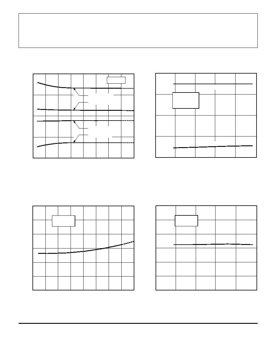
TYPICAL OPERATING CHARACTERISTICS
SWITCH POINTS
0
50
100
AMBIENT TEMPERATURE IN
∞
∞
∞
∞
C
-50
Dwg. GH-056
DIFFERENTIAL FLUX DENSITY IN GAUSS
50
100
0
-50
3060
RELEASE POINT
3059
V = 8 V
CC
150
-100
-25
25
75
125
3059
OPERATE POINT
3060
Dwg. GH-057
DIFFERENTIAL FLUX DENSITY IN GAUSS
10
20
0
-10
-20
0
SUPPLY VOLTAGE IN VOLTS
5
10
15
20
25
UGN/UGS3060KA
I = 20 mA
T = +25
∞
C
OUT
A
OPERATE POINT
RELEASE POINT
0
25
50
75
100
300
0
AMBIENT TEMPERATURE IN
∞
∞
∞
∞
C
200
100
-50
Dwg. GH-029-1
SATURATION VOLTAGE IN mV
150
-25
125
I = 20 mA
V = 12 V
OUT
CC
200
50
150
100
Dwg. GH-055
SATURATION VOLTAGE IN mV
0
SUPPLY VOLTAGE IN VOLTS
5
10
15
20
25
I = 20 mA
T = +25
∞
C
OUT
A
OUTPUT SATURATION VOLTAGE
3059
AND
3060
HALL-EFFECT
GEAR-TOOTH SENSORS
--AC COUPLED
115 Northeast Cutoff, Box 15036
Worcester, Massachusetts 01615-0036 (508) 853-5000
4
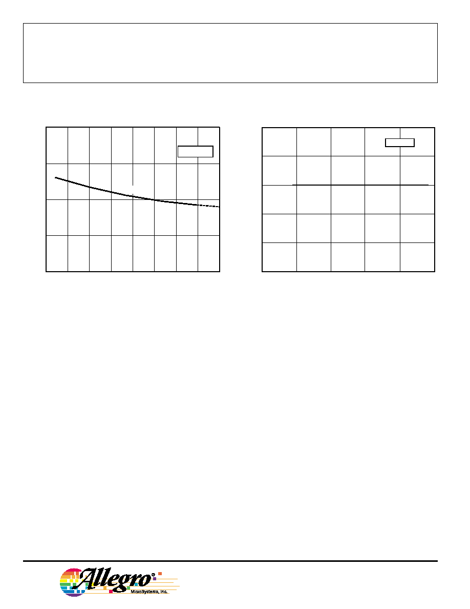
TYPICAL OPERATING CHARACTERISTICS
SUPPLY CURRENT
0
SUPPLY CURRENT IN mA
20
15
10
5
0
25
50
75
100
AMBIENT TEMPERATURE IN
∞
∞
∞
∞
C
-50
Dwg. GH-028-1
125
-25
V = 18 V
CC
150
B
B
RP
A gear-tooth sensing system consists of the sensor
IC, a back-biasing magnet, and a target. The system
requirements are usually specified in terms of the effective
working air gap between the package and the target (gear
teeth), the number of switching events per rotation of the
target, temperature and speed ranges, minimum pulse
duration or duty cycle, and switch point accuracy. Careful
choice of the sensor IC, magnet material and shape,
target material and shape, and assembly techniques
enables large working air gaps and high switch-point
accuracy over the system operating temperature range.
Naming Conventions. With a south pole in front of
the branded surface of the sensor or a north pole behind
the sensor, the field at the sensor is defined as positive.
As used here, negative flux densities are defined as less
than zero (algebraic convention), e.g., -100 G is less than
+50 G.
Magnet Biasing. In order to sense moving non-
magnetized ferrous targets, these devices must be back-
biased by mounting the unbranded side on a small
permanent magnet. Either magnetic pole (north or south)
can be used.
The devices can also be used without a back-biasing
magnet. In this configuration, the sensor can be used to
detect a rotating ring magnet such as those found in
brushless dc motors or in speed sensing applications.
Here, the sensor detects the magnetic field gradient
created by the magnetic poles.
APPLICATIONS INFORMATION
0
8
SUPPLY CURRENT IN mA
SUPPLY VOLTAGE IN VOLTS
Dwg. GH-031-1
13
12
11
10
9
5
10
15
20
25
T = +25
∞
C
A
B < B
RP

3059
AND
3060
HALL-EFFECT
GEAR-TOOTH SENSORS
--AC COUPLED
www.allegromicro.com
5
24 V
MAX
0
+B
0
OUTPUT VOLTAGE IN VOLTS
DIFFERENTIAL FLUX DENSITY, B
E1
≠ B
E2
Dwg. GH-034
-B
OP
RP
B
B
V
OUT(SAT)
Figure 2
OP
B
B ≠ B
E1 E2
GEAR
4300 G
4130 G
150 G
0 G
-150 G
RP
B
V
OUT(SAT)
V
OUT
B & B
E1 E2
OUTPUT DUTY CYCLE
50%
Dwg. WH-003-1
DIRECTION
OF ROTATION
LEADING
EDGE
TRAILING
EDGE
NORTH
SOUTH
E2
E1
(a)
(b)
(c)
Sensor Operation. These sensor ICs each contain
two integrated Hall transducers (E1 and E2) that are used
to sense a magnetic field differential across the face of the
IC (see Sensor Location drawing). Referring to Figure 1,
the trigger switches the output ON (output LOW) when
B
E1
- B
E2
<
B
OP
and switches the output OFF (output
HIGH) when B
E1
- B
E2
< B
RP
. The difference between B
OP
and B
RP
is the hysteresis of the device.
Figure 2 relates the output state of a back-biased
sensor IC, with switching characteristics shown in Figure
1, to the target gear profile and position. Assume a north
pole back-bias configuration (equivalent to a south pole at
the face of the device). The motion of the gear produces
a phase-shifted field at E1 and E2 (Figure 2(a)); internal
conditioning circuitry subtracts the fields at the two
elements (Figure 2(b)); this differential field is band-pass
filtered to remove dc offset components and then fed into
a Schmitt trigger; the Schmitt trigger switches the output
transistor at the thresholds B
OP
and B
RP
. As shown
(Figure 2(c)), the IC output is LOW whenever sensor E1
sees a (ferrous) gear tooth and sensor E2 faces air. The
output is HIGH when sensor E1 sees air and sensor E2
sees the ferrous target.
AC-Coupled Operation. Steady-state magnet and
system offsets are eliminated using an on-chip differential
band-pass filter. The lower frequency cut-off of this
patented filter is set using an external capacitor the value
of which can range from 0.01
µ
F to 10
µ
F. The high-
frequency cut-off of this filter is set at 30 kHz by an
internal integrated capacitor.
The differential structure of this filter enables the IC to
reject single-ended noise on the ground or supply line
and, hence, makes it resistant to radio-frequency and
electromagnetic interference typically seen in hostile
remote sensing environments. This filter configuration
also increases system tolerance to capacitor degradation
at high temperatures, allowing the use of an inexpensive
external ceramic capacitor.
Figure 1
TYPICAL TRANSFER
CHARACTERISTIC
APPLICATIONS INFORMATION (cont'd)
3059
AND
3060
HALL-EFFECT
GEAR-TOOTH SENSORS
--AC COUPLED
115 Northeast Cutoff, Box 15036
Worcester, Massachusetts 01615-0036 (508) 853-5000
6
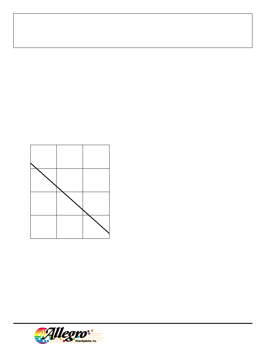
Low-Frequency Operation. Low-frequency opera-
tion of the sensor is set by the value of an external
capacitor. Figure 3 provides the low-frequency cut-off (-3
dB point) of the filter as a function of capacitance value.
This information should be used with care. The graph
assumes a perfect sinusoidal magnetic signal input.
In reality, when used with gear teeth, the teeth create
transitions in the magnetic field that have a much higher
frequency content than the basic rotational speed of the
target. This allows the device to sense speeds much
lower than those indicated by the graph for a given
capacitor value.
codes Z5S, Y5S, X5S, or X7S (depending on operating
temperature range) or better are recommended. The
commonly available Z5U temperature code should not be
used in this application.
Magnet Selection. The UGS3059KA or UGx3060KA
can be used with a wide variety of commercially available
permanent magnets. The selection of the magnet de-
pends on the operational and environmental requirements
of the sensing system. For systems that require high
accuracy and large working air gaps or
an extended temperature range, the usual magnet mate-
rial of choice is rare-earth samarium cobalt (SmCo). This
magnet material has a high energy product and can
operate over an extended temperature range. For sys-
tems that require low-cost solutions for an extended
temperature range, AlNiCo 8 can be used. Due to its
relatively low energy product, smaller operational air gaps
can be expected. Neodymium iron boron (NeFeB) can be
used over moderate temperature ranges when large
working air gaps are required. Of these three magnet
materials, AlNiCo 8 is the least expensive by volume and
SmCo is the most expensive.
System Issues. Optimal performance of a gear-tooth
sensing system strongly depends on four factors: the IC
magnetic parameters, the magnet, the pole piece configu-
ration, and the target.
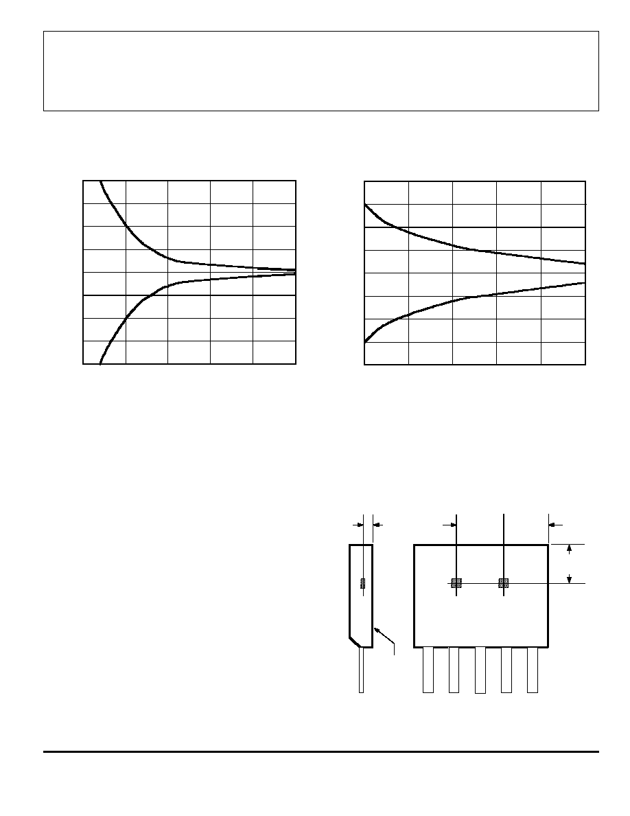
Sensor Specifications. Shown in Figure 4 are
graphs of the differential field as a function of air gap.
A 48-tooth, 2.5" (63.5 mm) diameter, uniform target similar
to that used in ABS applications is used. The samarium
cobalt magnet is 0.32" diameter by 0.20" long
(8.13 x 5.08 mm). The maximum functioning air gap with
this typical gear/magnet combination can be determined
using the graphs and specifications for the sensor IC.
In this case, if a UGx3060KA sensor with a typical B
OP
of 15 G and a B
RP
of -15 G is used, the maximum allow-
able air gap would be approximately 0.120". If the worst
case switch points of
±
35 G for the UGx3060KA are used,
the maximum air gap is approximately 0.105".
All system issues should be translated back to such a
profile to aid the prediction of system performance.
Figure 3
Capacitor Characteristics. The major requirement
for the external capacitor is its ability to operate in a
bipolar (non-polarized) mode. Another important require-
ment is the low leakage current of the capacitor (equiva-
lent parallel resistance should be greater than 500k
). To
maintain proper operation with frequency, capacitor
values should be held to within
±
30% over the operating
temperature range. Available non polarized capacitors
include ceramic, polyester, and some tantalum types. For
low-cost operation, ceramic capacitors with temperature
0.1
1.0
10
1.0
10
CAPACITANCE IN
µ
µ
µ
µ
F
100
0.1
0.01
Dwg. GH-025
LOW-FREQUENCY CUTOFF IN Hz
1 k
APPLICATIONS INFORMATION (cont'd)
3059
AND
3060
HALL-EFFECT
GEAR-TOOTH SENSORS
--AC COUPLED
www.allegromicro.com
7
Figure 4
DIFFERENTIAL FLUX DENSITY
0
-2000
AIRGAP FROM PACKAGE FACE IN INCHES
Dwg. GH-035
2000
1000
0
-1000
-1500
0.025
0.050
0.100
0.125
1500
0.075
-500
500
DIFFERENTIAL FLUX DENSITY IN GAUSS
Ferrous Targets. The best ferrous targets are made
of cold-rolled low-carbon steel. Sintered-metal targets are
also usable, but care must be taken to ensure uniform
material composition and density.
The teeth or slots of the target should be cut with a
slight angle so as to minimize the abruptness of transition
from metal to air as the target passes by the sensor.
Sharp transitions will result in magnetic overshoots that
can result in false triggering.
Gear teeth larger than 0.10" (2.54 mm) wide and at
least 0.10" (2.54 mm) deep provide reasonable working
air gaps and adequate change in magnetic field for
reliable switching. Generally, larger teeth and slots allow
a larger air gap. A gear tooth width approximating the
spacing between sensors (0.088" or 2.24 mm) requires
special care in the sytem design and assembly tech-
niques.
Figure 5
SENSOR LOCATIONS
(
±
0.005" [0.13 mm] die placement)
A
Dwg. MH-007E
0.0165"
0.42 mm
NOM
BRANDED
SURFACE
ACTIVE AREA DEPTH
0.087"
2.20 mm
1
2
4
5
3
E1
E2
0.083"
2.10 mm
0.075"
1.91 mm
0.070
-200
AIRGAP FROM PACKAGE FACE IN INCHES
Dwg. GH-036
200
100
0
-100
-150
0.080
0.090
0.110
0.120
150
0.100
-50
50
DIFFERENTIAL FLUX DENSITY IN GAUSS
A
APPLICATIONS INFORMATION (cont'd)

3059
AND
3060
HALL-EFFECT
GEAR-TOOTH SENSORS
--AC COUPLED
115 Northeast Cutoff, Box 15036
Worcester, Massachusetts 01615-0036 (508) 853-5000
8
The products described herein are manufactured under one or
more of the following U.S. patents: 5,045,920; 5,264,783; 5,442,283;
5,389,889; 5,581,179; 5,517,112; 5,619,137; 5,621,319; 5,650,719;
5,686,894; 5,694,038; 5,729,130; 5,917,320; and other patents
pending.
Allegro MicroSystems, Inc. reserves the right to make, from time to
time, such departures from the detail specifications as may be
required to permit improvements in the performance, reliability, or
manufacturability of its products. Before placing an order, the user is
cautioned to verify that the information being relied upon is current.
Allegro products are not authorized for use as critical components
in life-support appliances, devices, or systems without express written
approval.
The information included herein is believed to be accurate and
reliable. However, Allegro MicroSystems, Inc. assumes no responsi-
bility for its use; nor for any infringements of patents or other rights of
third parties that may result from its use.
APPLICATIONS INFORMATION (cont'd)
Extensive applications information for Hall-effect sensors is available in:
∑ Hall-Effect IC Applications Guide, Application Note 27701;
∑ Hall-Effect Devices: Soldering, Gluing, Potting, Encapsulating, and Lead Forming, Application Note 27703.1;
∑ Soldering of Through-Hole Hall-Sensor Dervices, Application Note 27703; and
∑ Soldering of Surface-Mount Hall-Sensor Devices, Application Note 27703.2.
All are provided in Allegro Electronic Data Book, AMS-702. or at
www.allegromicro.com
3059
AND
3060
HALL-EFFECT
GEAR-TOOTH SENSORS
--AC COUPLED
www.allegromicro.com
9
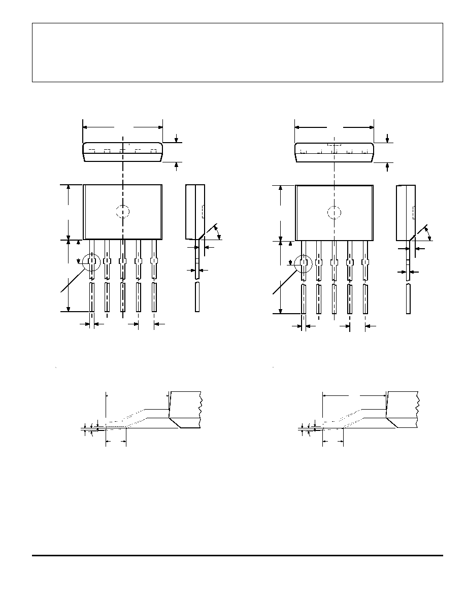
NOTES: 1. Tolerances on package height and width represent allowable mold offsets. Dimensions given are measured at the widest point (parting
line).
2. Exact body and lead configuration at vendor's option within limits shown.
3. Height does not include mold gate flash.
4. Recommended minimum PWB hole diameter to clear transition area is 0.035" (0.89 mm).
5. Where no tolerance is specified, dimension is nominal.
6. Supplied in bulk pack (500 pieces per bag).
Surface-Mount Lead Form (Suffix -TL)
2.41
±
0.13
0.51
MIN
FLAT
Dwg. MH-015 mm
0.10
MAX
0.051
MAX
0
∞
≠8
∞
0.095
±
0.005
0.020
MIN
FLAT
Dwg. MH-015 in
0.004
MAX
0.002
MAX
0
∞
≠8
∞
Dwg. MH-010H in
0.018
0.0173
0.0138
0.0189
0.0142
0.050
BSC
1
3
4
5
2
0.063
0.059
45
∞
0.600
0.560
0.083
MAX
0.252
0.247
0.181
0.176
SEE NOTE
Dimensions in Inches
(controlling dimensions)
Dimensions in Millimeters
(for reference only)
Dwg. MH-010H mm
0.46
0.44
0.35
0.48
0.36
1.27
BSC
1
3
4
5
2
1.60
1.50
45
∞
15.24
14.23
2.11
MAX
6.40
6.27
4.60
4.47
SEE NOTE

3059
AND
3060
HALL-EFFECT
GEAR-TOOTH SENSORS
--AC COUPLED
115 Northeast Cutoff, Box 15036
Worcester, Massachusetts 01615-0036 (508) 853-5000
10
HALL-EFFECT SENSORS
DUAL-OUTPUT HALL-EFFECT DIGITAL SWITCHES
Partial
Operate
Release
Hysteresis
Part
Point (G)
Point (G)
(G)
Oper.
Number
Over Oper. Voltage & Temp. Range
Temp.
Package
Comments
UGN3235
35 to 200
15 to 190
15 to 110
S
K
independent
-200 to -35
-190 to -15
15 to 110
switch outputs
UGN3275
15 to 250
-250 to -15
>100
S
K
complementary latch outputs
DIRECTION-DETECTING HALL-EFFECT DIGITAL SWITCHES
Partial
Operate
Release
Hysteresis
Part
Point (G)
Point (G)
(G)
Oper.
Number
Over Oper. Voltage & Temp. Range
Temp.
Package
Comments
A3422x
<85
>-85
>10
E, L
KA
direction and speed outputs
A3425L
<30
>-30
5 to 35
L
K
requires external logic
GEAR-TOOTH/RING MAGNET (DUAL ELEMENT) HALL-EFFECT SENSORS
See also, Adaptive Threshold Sensors (subassemblies containg sensor and magnet)
Partial
Operate
Release
Hysteresis
Change in
Part
Point (G)
Point (G)
(G)
Trip Point (G)
Oper.
Number
Over Oper. Voltage & Temp. Range
Temp.
Package
Comments
A3056x
<150
>-150
15 to 90
<
±
75
E, L
U
zero-speed
A3058x
<250
>-250
150 to 250
<
±
50
E, L
U
zero-speed
UGS3059
10 to 100
-100 to -10
Typ130
--
S, K
KA
>0.2 Hz
UGx3060
5 to 35
-35 to -5
Typ 30
--
S, K
KA
>0.2 Hz
A3064L
0 to 27.5
-12.5 to 7.5
5 to 35
--
L
KA
>0.2 Hz
Notes: 1) Typical data is at TA = +25
∞
C and nominal operating voltage.
2) "x" = Operating Temperature Range [suffix letter or (prefix)]: S (UGN) = -20
∞
C to +85
∞
C, E = -40
∞
C to +85
∞
C,
J = -40
∞
C to +115
∞
C, K (UGS) = -40
∞
C to +125
∞
C, L (UGL) = -40
∞
C to +150
∞
C.