
HIGH-VOLTAGE, HIGH-CURRENT
DARLINGTON ARRAYS
FEATURES
s TTL, DTL, PMOS, or CMOS Compatible Inputs
s Output Current to 500 mA
s Output Voltage to 95 V
s Transient-Protected Outputs
s Dual In-Line Package or Wide-Body Small-Outline Package
Data Sheet
29304.3E*
Featuring continuous load current ratings to 500 mA for each of
the drivers, the Series ULN28xxA/LW and ULQ28xxA/LW high-
voltage, high-current Darlington arrays are ideally suited for interfac-
ing between low-level logic circuitry and multiple peripheral power
loads. Typical power loads totaling over 260 W (350 mA x 8, 95 V)
can be controlled at an appropriate duty cycle depending on ambient
temperature and number of drivers turned on simultaneously. Typical
loads include relays, solenoids, stepping motors, magnetic print ham-
mers, multiplexed LED and incandescent displays, and heaters. All
devices feature open-collector outputs with integral clamp diodes.
The ULx2803A, ULx2803LW, ULx2823A, and ULN2823LW
have series input resistors selected for operation directly with 5 V TTL
or CMOS. These devices will handle numerous interface needs --
particularly those beyond the capabilities of standard logic buffers.
The ULx2804A, ULx2804LW, ULx2824A, and ULN2824LW
have series input resistors for operation directly from 6 V to 15 V
CMOS or PMOS logic outputs.
The ULx2803A/LW and ULx2804A/LW are the standard
Darlington arrays. The outputs are capable of sinking 500 mA and will
withstand at least 50 V in the off state. Outputs may be paralleled for
higher load current capability. The ULx2823A/LW and ULx2824A/
LW will withstand 95 V in the off state.
These Darlington arrays are furnished in 18-pin dual in-line
plastic packages (suffix `A') or 18-lead small-outline plastic packages
(suffix `LW'). All devices are pinned with outputs opposite inputs to
facilitate ease of circuit board layout. Prefix `ULN' devices are rated
for operation over the temperature range of -20
∞
C to +85
∞
C; prefix
`ULQ' devices are rated for operation to -40
∞
C.
x = Character to identify specific device. Characteristic shown applies to family
of devices with remaining digits as shown. See matrix on next page.
2803
THRU
2824
18
17
15
14
13
7
12
8
11
9
10
1
2
4
5
6
Dwg. No. A-10,322A
16
3
ABSOLUTE MAXIMUM RATINGS
Output Voltage, V
CE
(x2803x and x2804x) ..................... 50 V
(x2823x and x2824x) ..................... 95 V
Input Voltage, V
IN
.............................. 30 V
Continuous Output Current, I
C
.... 500 mA
Continuous Input Current, I
IN
....... 25 mA
Power Dissipation, P
D
(one Darlington pair) .................. 1.0 W
(total package) ..................... See Graph
Operating Temperature Range, T
A
Prefix `ULN' .............. -20
∞
C to + 85
∞
C
Prefix `ULQ' ............... -40
∞
C to +85
∞
C
Storage Temperature Range,
T
S
................................ -55
∞
C to +150
∞
C
Note that the ULx28xxA series (dual in-line
package) and ULx28xxLW series (small-
outline IC package) are electrically identical
and share a common terminal number assign-
ment.
The ULx2804, ULx2823, & ULx2824 are discontinued.
Shown for reference only.
2803
THRU
2824
HIGH-VOLTAGE,
HIGH-CURRENT
DARLINGTON ARRAYS
115 Northeast Cutoff, Box 15036
Worcester, Massachusetts 01615-0036 (508) 853-5000
2
ULx28x4A/LW (Each Driver)
Copyright © 1977, 2001 Allegro MicroSystems, Inc.
V
CE(MAX)
50 V
95 V
I
C(MAX)
500 mA
500 mA
Logic
Part Number
5V
ULN2803A*
ULN2823A*
TTL, CMOS
ULN2803LW*
ULN2823LW
6-15 V
ULN2804A*
ULN2824A*
CMOS, PMOS
ULN2804LW*
ULN2824LW
* Also available for operation between -40
∞
C and +85
∞
C. To order, change
prefix from `ULN' to `ULQ'.
DEVICE PART NUMBER DESIGNATION
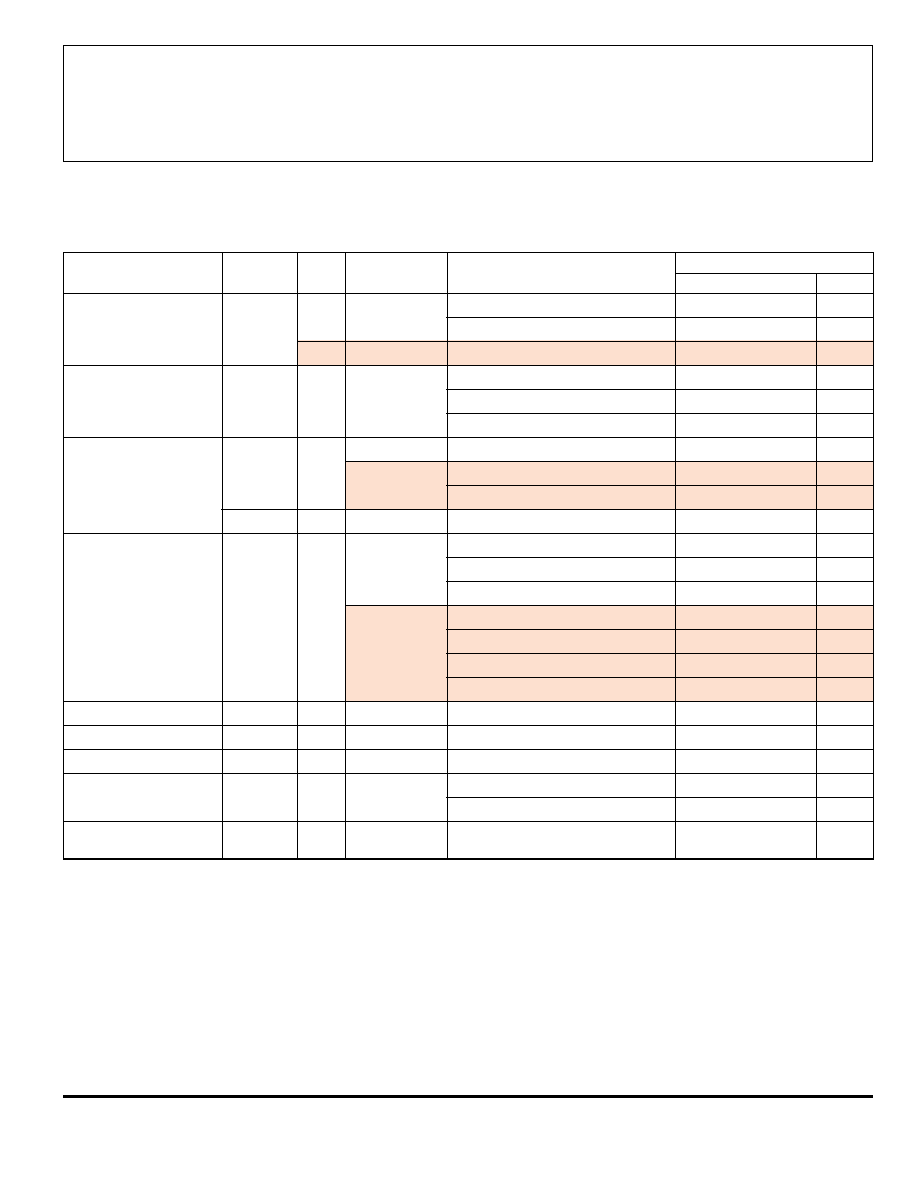
50
75
100
125
150
2.5
0.5
0
AMBIENT TEMPERATURE IN
∞
∞
∞
∞
C
2.0
1.5
1.0
25
Dwg. GP-018B
SUFFIX 'A', R = 60
∞
C/W
JA
SUFFIX 'LW', R = 80
∞
C/W
JA
ALLOWABLE PACKAGE POWER DISSIPATION IN WATTS
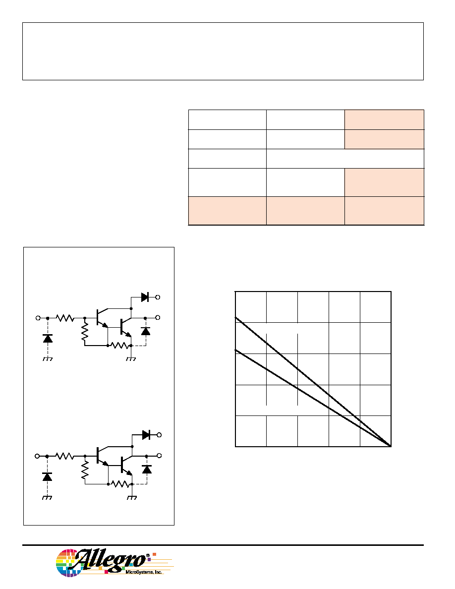
ULx28x3A/LW (Each Driver)
PARTIAL SCHEMATICS
x = Character to identify specific device. Specification shown applies to
family of devices with remaining digits as shown. See matrix above.
The ULx2804, ULx2823, & ULx2824 are discontinued.
Shown for reference only.
Dwg. FP-052-2
3 K
7.2 K
2.7 K
Dwg. FP-052-3
3 K
7.2 K
10.5 K
2803
THRU
2824
HIGH-VOLTAGE,
HIGH-CURRENT
DARLINGTON ARRAYS
www.allegromicro.com
3
Test
Applicable
Limits
Characteristic
Symbol
Fig.
Devices
Test Conditions
Min.
Typ.
Max.
Units
Output Leakage Current
I
CEX
1A
All
V
CE
= 50 V, T
A
= 25
∞
C
--
< 1
50
µ
A
V
CE
= 50 V, T
A
= 70
∞
C
--
< 1
100
µ
A
1B
ULx2804x
V
CE
= 50 V, T
A
= 70
∞
C, V
IN
= 1.0 V
--
< 5
500
µ
A
Collector-Emitter
V
CE(SAT)
2
All
I
C
= 100 mA, I
B
= 250
µ
A
--
0.9
1.1
V
Saturation Voltage
l
C
= 200 mA, I
B
= 350
µ
A
--
1.1
1.3
V
I
C
= 350 mA, I
B
= 500
µ
A
--
1.3
1.6
V
Input Current
I
IN(ON)
3
ULx2803x
V
IN
= 3.85 V
--
0.93
1.35
mA
ULx2804x
V
IN
= 5.0 V
--
0.35
0.5
mA
V
IN
= 12 V
--
1.0
1.45
mA
I
IN(OFF)
4
All
l
C
= 500
µ
A, T
A
= 70
∞
C
50
65
--
µ
A
Input Voltage
V
IN(ON)
5
ULx2803x
V
CE
= 2.0 V, l
C
= 200 mA
--
--
2.4
V
V
CE
= 2.0 V, I
C
= 250 mA
--
--
2.7
V
V
CE
= 2.0 V, l
C
= 300 mA
--
--
3.0
V
ULx2804x
V
CE
= 2.0 V, l
C
= 125 mA
--
--
5.0
V
V
CE
= 2.0 V, l
C
= 200 mA
--
--
6.0
V
V
CE
= 2.0 V, I
C
= 275 mA
--
--
7.0
V
V
CE
= 2.0 V, l
C
= 350 mA
--
--
8.0
V
Input Capacitance
C
IN
--
All
--
15
25
pF
Turn-On Delayt
PLH
8
All
0.5 E
IN
to 0.5 E
OUT
--
0.25
1.0
µ
s
Turn-Off Delayt
PHL
8
All
0.5 E
IN
to 0.5 E
OUT
--
0.25
1.0
µ
s
Clamp Diode
I
R
6
All
V
R
= 50 V, T
A
= 25
∞
C
--
--
50
µ
A
Leakage Current
V
R
= 50 V, T
A
= 70
∞
C
--
--
100
µ
A
Clamp Diode
V
F
7
All
I
F
= 350 mA
--
1.7
2.0
V
Forward Voltage
Complete part number includes prefix to operating temperature range: ULN = -20
∞
C to +85
∞
C, ULQ = -40
∞
C to +85
∞
C
and a suffix to identify package style: A = DIP, LW = SOIC.
Types ULx2803A, ULx2803LW, ULx2804A, and ULx2804LW
ELECTRICAL CHARACTERISTICS at +25
∞
C (unless otherwise noted).
The ULx2804 is discontinued.
Shown for reference only.

2803
THRU
2824
HIGH-VOLTAGE,
HIGH-CURRENT
DARLINGTON ARRAYS
115 Northeast Cutoff, Box 15036
Worcester, Massachusetts 01615-0036 (508) 853-5000
4
Test
Applicable
Limits
Characteristic
Symbol
Fig.
Devices
Test Conditions
Min.
Typ.
Max.
Units
Output Leakage Current
I
CEX
1A
All
V
CE
= 95 V, T
A
= 25
∞
C
--
< 1
50
µ
A
V
CE
= 95 V, T
A
= 70
∞
C
--
< 1
100
µ
A
1B
ULx2824x
V
CE
= 95 V, T
A
= 70
∞
C, V
IN
= 1.0 V
--
< 5
500
µ
A
Collector-Emitter
V
CE(SAT)
2
All
I
C
= 100 mA, I
B
= 250
µ
A
--
0.9
1.1
V
Saturation Voltage
l
C
= 200 mA, I
B
= 350
µ
A
--
1.1
1.3
V
I
C
= 350 mA, I
B
= 500
µ
A
--
1.3
1.6
V
Input Current
I
IN(ON)
3
ULx2823x
V
IN
= 3.85 V
--
0.93
1.35
mA
ULx2824x
V
IN
= 5.0 V
--
0.35
0.5
mA
V
IN
= 12 V
--
1.0
1.45
mA
I
IN(OFF)
4
All
l
C
= 500
µ
A, T
A
= 70
∞
C
50
65
--
µ
A
Input Voltage
V
IN(ON)
5
ULx2823x
V
CE
= 2.0 V, l
C
= 200 mA
--
--
2.4
V
V
CE
= 2.0 V, I
C
= 250 mA
--
--
2.7
V
V
CE
= 2.0 V, l
C
= 300 mA
--
--
3.0
V
ULx2824x
V
CE
= 2.0 V, l
C
= 125 mA
--
--
5.0
V
V
CE
= 2.0 V, l
C
= 200 mA
--
--
6.0
V
V
CE
= 2.0 V, I
C
= 275 mA
--
--
7.0
V
V
CE
= 2.0 V, l
C
= 350 mA
--
--
8.0
V
Input Capacitance
C
IN
--
All
--
15
25
pF
Turn-On Delayt
PLH
8
All
0.5 E
IN
to 0.5 E
OUT
--
0.25
1.0
µ
s
Turn-Off Delayt
PHL
8
All
0.5 E
IN
to 0.5 E
OUT
--
0.25
1.0
µ
s
Clamp Diode
I
R
6
All
V
R
= 95 V, T
A
= 25
∞
C
--
--
50
µ
A
Leakage Current
V
R
= 95 V, T
A
= 70
∞
C
--
--
100
µ
A
Clamp Diode
V
F
7
All
I
F
= 350 mA
--
1.7
2.0
V
Forward Voltage
Complete part number includes prefix to operating temperature range: ULN = -20
∞
C to +85
∞
C, ULQ = -40
∞
C to +85
∞
C
and a suffix to identify package style: A = DIP, LW = SOIC. Note that the ULQ2823LW and ULQ2824LW are not presently
available.
Types ULx2823A, ULN2823LW, ULx2824A, and ULN2824LW
ELECTRICAL CHARACTERISTICS at +25
∞
C (unless otherwise noted).
The ULx2823 & ULx2824 are discontinued.
Shown for reference only.
