Alpha Industries, Inc. [781] 935-5150
∑
Fax [617] 824-4579
∑
Email sales@alphaind.com
∑
www.alphaind.com
1
Specifications subject to change without notice. 3/99A
GaAs 30 dB IC Voltage Variable Dual
Control Attenuator DC≠4 GHz
Features
s
Dual Control Voltages
s
Low Insertion Loss
s
8 Lead Hermetic Surface Mount Package
s
Capable of Meeting MIL-STD
Requirements
5
-11
AT004N3-11
Description
The AT004N3-11 is a GaAs IC FET non-reflective bridged
"T" attenuator. This device provides over 30 dB of
"matched" attenuation with the input and output VSWR
less than 1.5:1 under all attenuation values. The
applications for these fast attenuators are AGC circuits and
variable level control in high reliability and
telecommunication systems.
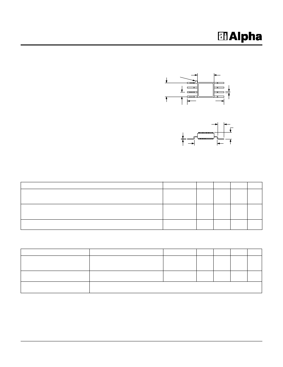
0.180 (4.57 mm)
SQ. MAX.
0.400 (10.16 mm)
0.380 (9.65 mm)
0.150
(3.81 mm)
0.050
(1.27 mm)
TYP.
ORIENTATION
MARK
0.017 (0.43 mm)
0.013 (0.33 mm)
0.006 (0.15 mm)
0.004 (0.10 mm)
0.250 (6.35 mm)
0.200 (5.08 mm)
0.070 (1.78 mm)
0.040 (1.02 mm)
0.075
(1.91 mm)
MAX.
1. All measurements made in a 50
system, unless otherwise specified.
2. Insertion loss changes by 0.003 dB/∞C.
3. Video feedthru measured with 1 ns risetime pulse and 500 MHz bandwidth.
4. DC = 300 kHz.
5. See Quality/Reliability section.
Parameter
Condition
Frequency
Min.
Typ.
Max.
Unit
Switching Characteristics
Rise, Fall (10/90% or 90/10% RF)
7
ns
On, Off (50% CTL to 90/10% RF)
10
ns
Video Feedthru
3
20
mV
Input Power for 1 dB Compression
For All Attenuation Levels
0.5≠4 GHz
0
dBm
0.05 GHz
-3
dBm
Control Voltages
V
Low
= 0 to -0.2 V @ 20
µ
A Max.
V
High
= -5 V @ 50
µ
A Max.
Operating Characteristics at 25∞C
Parameter
1
Frequency
4
Min.
Typ.
Max.
Unit
Insertion Loss
2
DC≠1.0 GHz
0.8
1.0
dB
DC≠2.0 GHz
1.0
1.2
dB
DC≠4.0 GHz
1.2
1.4
dB
Attenuation Range
DC≠1.0 GHz
30
35
dB
DC≠2.0 GHz
29
33
dB
DC≠4.0 GHz
26
30
dB
VSWR (I/O)
DC≠2.0 GHz
1.25:1
1.3:1
DC≠4.0 GHz
1.40:1
1.5:1
Electrical Specifications at 25∞C

GaAs 30 dB IC Voltage Variable Dual Control Attenuator DC≠4 GHz
AT004N3-11
2
Alpha Industries, Inc. [781] 935-5150
∑
Fax [617] 824-4579
∑
Email sales@alphaind.com
∑
www.alphaind.com
Specifications subject to change without notice. 3/99A
Insertion Loss vs. Frequency
Frequency (GHz)
0.4
DC
3
1
2
4
0.8
1.2
1.5
2.0
I
n
s
e
r
t
i
o
n
L
o
s
s
(
d
B
)
2.4
+85∞C
-55∞C
Relative Attenuation vs. Control Voltages
Relative Attenuation (dB)
-5.0
0
5
F = 1 GHz, V
P
1
= -3.5 V
10
15
20
25
30
35
-4.0
-3.0
-2.0
-1.0
V
1
V
2
C
o
n
t
r
o
l
V
o
l
t
a
g
e
s
(
V
)
0
V
1
(Series)
V
2
(Shunt)
Attenuation vs. 1.0 dB Compression Point
Attenuation (dB)
-5
0
5
F = 50 MHz
10
15
20
25
30
0
5
10
15
P
I
N
a
t
1
.
0
d
B
C
o
m
p
r
e
s
s
i
o
n
(
d
B
m
)
20
Attenuation (By State) vs. Frequency
Frequency (GHz)
0
DC
3
1
2
4
10
20
30
40
A
t
t
e
n
u
a
t
i
o
n
(
d
B
)
50
Typical Performance Data
Typical Transfer Curve
Pin Out
J
1
GND
GND
V
2
V
1
GND
GND
J
2
Characteristic
Value
RF Input Power (RF In)
10 mW > 500 MHz
4 mW @ 50 MHz
Control Voltage (V
C
)
+0.2 V, -10 V
Operating Temperature (T
OP
)
-55∞C to +125∞C
Storage Temperature (T
ST
)
-65∞C to +150∞C
Thermal Resistance (
JC
)
25∞C/W
Absolute Maximum Ratings
Attenuation
V
1
V
2
J
1
≠J
2
0
-5
Insertion Loss
-5
0
Full Attenuation
Truth Table