
Alpha Industries, Inc. [781] 935-5150
∑ Fax [617] 824-4579 ∑ Email sales@alphaind.com ∑ www.alphaind.com
1
Specifications subject to change without notice. 3/00A
GaAs Flip Chip Schottky Diodes
Features
I Designed for High Volume Designs
I High Frequency (20≠100 GHz)
I Exceeds Environmental Requirements for
MIC & Hybrid Applications
I Designed for Low Junction Capacitance
and Low Series Resistance
I Applications Include PCN Mixers and
Circuits, As Well As Low Power, Fast
Switching
I Low Parasitic Flip Chip Configuration
Description
This new series of GaAs Schottky barrier diodes offer high
performance at commercial market prices. They are
designed for low junction capacitance, as well as low series
resistance. Diodes are designed for MIC work (hard and soft
substrates), but the leadless design eliminates the
problems associated with mounting of beam lead diodes.
Due to its rigid construction, it exceeds environmental
requirements for MIC and hybrid applications. Diodes can
be supplied on expandable film frame for high speed pick
and place process. Standard packing will be in a gel pack.
Flexible conductive epoxy is the most effective
method for circuitry attachments. Standard mounting
temperatures should not exceed 175∞C.
Single - DMK2783-000, DMK2790-000
Anti-Parallel - DMK2308-000
Series Pair - DMK8001-000
Electrical Specifications at 25∞C
1. V
B
cannot be measured nondestructively in anti-parallel configuration.
2. C
T
= junction capacitance plus 0.02 pF (overlay).
Recommended
V
B
1
C
T
2
Frequency
@ 10
µ
µA
0 V, 1 MHz
R
S
@ 10 mA
V
F
@ 1 mA
Single
Series Pair
Anti-Parallel
(GHz)
(V)
(pF)
(
)
(mV)
Min.
Max.
Max.
Min.
Max.
540-011
540-012
540-025
20≠100
3.0
0.03
0.05
9
680
780
DMK2783-000
20≠100
3.0
0.04
0.07
7
650
750
DMK2790-000
DMK2308-000
20≠100
3.0
0.05
0.08
7
650
750
DMK8001-000
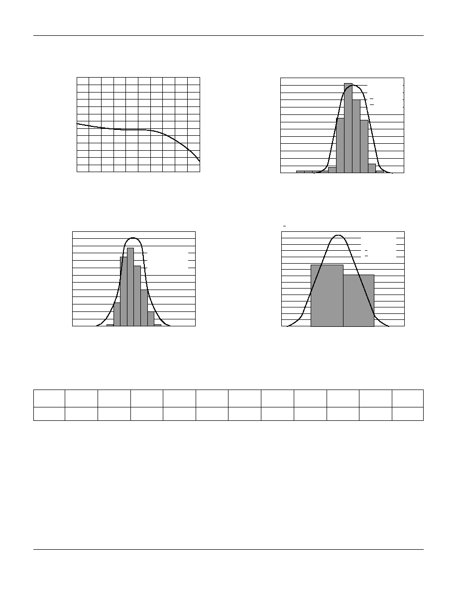
Histogram
V
F
1 mA (mV)
680
700
720
740
Number of Obs
0
5
10
15
20
25
30
35
40
45
50
55
60
65
V
F
= Mixer
DMK2790
x = 719 mV
= 6.3 mV
Capacitance/Voltage Variation
Bias Voltage (V)
0
0.5 1.0 1.5 2.0 2.5 3.0 3.5 4.0 4.5 5.0
De
vice Capacitance (pF)
0.028
0.032
0.036
0.040
0.044
0.048
0.052
0.056
0.060
0.064
0.068
0.072
0.076
0.080
Histogram
R
T
10 mA (
)
4.0
4.5
5.0
5.5
6.0
Number of Obs
0
11
22
33
44
55
66
77
88
99
110
121
132
143
154
165
R
T
= Mixer
DMK2790
x = 5.0
= 0.25
x = 5.0
= 0.25
Histogram
Capacitance 0 V (pF)
0.055
0.060
0.065
0.070
Number of Obs
0
5
10
15
20
25
30
35
40
45
50
55
60
Aug 0.063 pF SD = 0.002 pF
C
J
0.0063 pF
Average
0.0014 pF SD
Typical Parameter Distribution on Wafer
GaAs Flip Chip Schottky Diodes
2
Alpha Industries, Inc. [781] 935-5150
∑ Fax [617] 824-4579 ∑ Email sales@alphaind.com ∑ www.alphaind.com
Specifications subject to change without notice. 3/00A
Spice Parameters (Per Junction)
I
S
R
S
T
D
C
J
0
E
G
V
J
B
V
I
BV
Amp
n
S
pF
m
eV
eV
X
TI
FC
V
A
0.5 E≠12
4 1.05
1E≠11 0.05 0.26 1.43 0.82
2
0.5
4.0 1E≠05

GaAs Flip Chip Schottky Diodes
Alpha Industries, Inc. [781] 935-5150
∑ Fax [617] 824-4579 ∑ Email sales@alphaind.com ∑ www.alphaind.com
3
Specifications subject to change without notice. 3/00A
Flexible Conductive Epoxy Mounting of
Alpha Beamless Flip Chip Diodes ≠ To
Soft or Hard Substrate ≠ As Plated
Deposit Conductive Epoxy
Cure Epoxy & DC Continuity Check
∑ Inspect for Adequate Epoxy Fillet
∑ Cure According to Mfg. Preferred Schedule.
Typically 110≠150∞C @ 60 Minutes, or 150∞C,
4 Minutes for Snap-Cure Epoxies
10 Mil Gap
Excessive
Epoxy Runout
Acceptable
Epoxy Runout
Conductive Epoxy
Drops (Minimum Amount)
Approximately 8 mil Diameter
1≠2 mil height
Perform Die Attach
∑ Flip Device
∑ Align Bond Pads to Epoxy Dot
(Alignment Marks Help)
∑ Use Even Pressure to Make Correct Connection
Suggested Setup Values For WEST-BOND
Model 7200A Epoxy Die Bonder
Materials
Epoxy
Microelectronic grade one component, solvent-free
silver-filled, electrically conductive adhesive -- example:
Ablebond 8380 by Ablestick.
Dispense Tube
WEST-BOND B-1831-1 with 9.5 mil I.D., or WEST-BOND
B-1831-2 with 15.5 mil I.D. Other sizes available.
Die Pickup Tool
SPT Part Number 2101-W625-CT-031 x 0.016 x 0.0075.
Hole diameter 0.016" face diameter 0.031", O.D. 0.625".
Use vacuum pressure to pick and place chip.
Adjustment
Bond Force
35 grams at tool.
Dispense Air
30 psi.
Dispense Time
To give diameter of dot required.
Curing Time
Temperature
Time
250∞C
10 min.
130∞C
20 min.
100∞C
60 min.
85∞C
120 min.
GaAs Flip Chip Schottky Diodes
4
Alpha Industries, Inc. [781] 935-5150
∑ Fax [617] 824-4579 ∑ Email sales@alphaind.com ∑ www.alphaind.com
Specifications subject to change without notice. 3/00A
0.008
(0.20 mm)
± 0.001
(0.025 mm)
0.005 (0.13 mm)
± 0.001 (0.025 mm)
0.026 (0.66 mm)
± 0.001 (0.025 mm)
0.013 (0.33 mm)
± 0.001 (0.025 mm)
0.013
(0.33 mm)
± 0.001
(0.025 mm)
0.005 (0.13 mm)
± 0.001 (0.025 mm)
MAX.
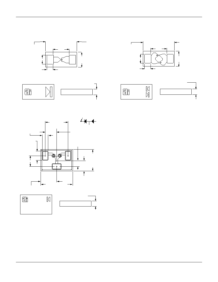
Outline Drawings
540-011
C
L
0.005 (0.127 mm)
± 0.001 (0.025 mm)
0.008
(0.203 mm)
± 0.001
(0.025 mm)
TYP.
0.005
(0.127 mm)
± 0.001
(0.025 mm)
TYP.
3
2
1
0.009
(0.229 mm)
± 0.001
(0.025 mm)
0.019
(0.483 mm)
± 0.001
(0.025 mm)
0.009 (0.229 mm)
± 0.001 (0.025 mm)
L
C
0.020 (0.508 mm)
± 0.001 (0.025 mm)
0.010 (0.254 mm)
± 0.001 (0.025 mm)
0.028 (0.711 mm)
± 0.001 (0.025 mm)
0.014 (0.356 mm)
± 0.001 (0.025 mm)
3
2
1
CATHODE LEAD
SCHEMATIC
0.005 (0.13 mm)
± 0.001 (0.025 mm) MAX.
540-012
0.008
(0.20 mm)
± 0.001
(0.025 mm)
0.005 (0.13 mm)
± 0.001 (0.025 mm)
0.026 (0.66 mm)
± 0.001 (0.025 mm)
0.013 (0.33 mm)
± 0.001 (0.025 mm)
0.013
(0.33 mm)
± 0.001
(0.025 mm)
0.005 (0.13 mm)
± 0.001 (0.025 mm) MAX.
540-025