
Alpha Industries, Inc. [781] 935-5150
∑
Fax [617] 824-4579
∑
Email sales@alphaind.com
∑
www.alphaind.com
1
Specifications subject to change without notice. 1/01A
Low Resistance Low Capacitance
Plastic Packaged PIN Diodes
Features
s
Designed for High Performance Wireless
Switch Applications
s
0.9
Resistance, 0.3 pF Capacitance
s
Multiple Package Configurations
s
Available in Tape and Reel Packaging
Description
The SMP1320 series of plastic packaged, surface
mountable PIN diodes are designed for high volume switch
applications from 10 MHz to beyond 2 GHz. The low
current performance of these diodes (0.9
maximum at
10 mA and 2
typical at 1 mA) make the SMP1320 series
particularly suited to battery operated circuits. Available
in a selection of plastic packages and in a variety of
configurations including a low inductance (0.4 nH)
SOT-23 (SMP1320-007), the small footprint SC-79 and the
miniature SC-70.
SMP1320 Series
Parameter
Condition
Typ.
Max.
Unit
Reverse Current (I
R
)
V
R
= 50 V
10
µ
A
Capacitance (C
T
)
F = 1 MHz, V = 30 V
0.30
pF
Resistance (R
S
)
F = 100 MHz, I = 1 mA
2.0
Resistance (R
S
)
F = 100 MHz, I = 10 mA
0.9
Forward Voltage (V
F
)
IF = 10 mA
0.85
V
Carrier Lifetime (TI)
IF = 10 mA
0.4
µ
S
I Region Width
8
µ
m
Electrical Specifications at 25∞C
Characteristic
Value
Reverse Voltage (V
R
)
50 V
Power Dissipation @ 25∞C Lead
250 mW
Temperature (P
D
)
Storage Temperature (T
ST
)
-65∞C to +150∞C
Operating Temperature (T
OP
)
-65∞C to +150∞C
ESD Human Body Model
Class 1B
Absolute Maximum Ratings
Single
Common Series
Pair
Low
Single
Ultra
Low
Single
Cathode
Inductance
Inductance
Marking: PL1
Marking: PL3
Marking: PL2
Marking: PLB
Marking: PLC
SOT-23
SOT-23
SOT-23
SOT-23
SOD-323
SOT-143
SC-79
o
SMP1320-001
o
SMP1320-004
o
SMP1320-005
o
SMP1320-007
o
SMP1320-011
o
SMP1320-017
o
SMP1320-079
L
S
= 1.5 nH
L
S
= 1.5 nH
L
S
= 1.5 nH
L
S
= 0.4 nH
L
S
= 1.5 nH
L
S
= 0.2 nH
L
S
= 0.7 nH
SC-70
SC-70
SC-70
o
SMP1320-074
o
SMP1320-075
o
SMP1320-077
L
S
= 1.4 nH
L
S
= 1.4 nH
L
S
= 0.4 nH
o
Available through distribution.
2
Alpha Industries, Inc. [781] 935-5150
∑
Fax [617] 824-4579
∑
Email sales@alphaind.com
∑
www.alphaind.com
Specifications subject to change without notice. 1/01A
Low Resistance Low Capacitance Plastic Packaged PIN Diodes
SMP1320 Series
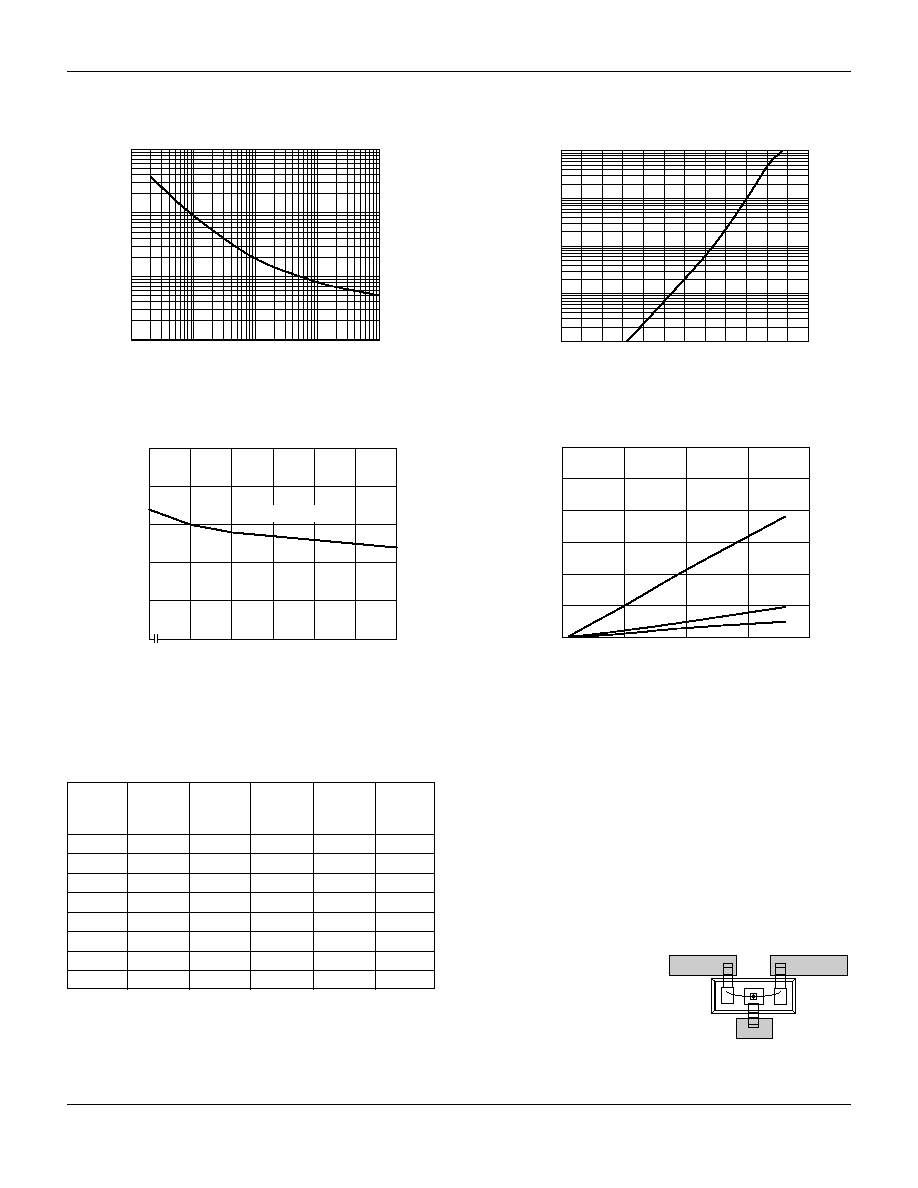
Series Resistance vs. Current @ 100 MHz
0.1
0.01
0.1
1
10
100
1
10
100
Forward Current (mA)
Series Resistance (
)
Capacitance vs. Reverse Voltage
Reverse Voltage (V)
Capacitance (pF)
0
0.1
0.2
0.3
0.4
0.5
0
1
2
5
10
20
50
1 MHz≠1 GHz
400
500
600
700
800
900
1000
DC Characteristic
0.01
0.1
1
10
100
Forward Voltage (mV)
Forward Current (mA)
0
500
1000
1500
2000
Conductance vs. Frequency
and Reverse Voltage
0
100
200
300
400
500
600
Frequency (MHz)
Conductance (
µ
S)
0 V
10 V
40 V
Typical Performance Data
R
S
R
S
R
S
R
S
R
S
I
F
-55∞C
-15∞C
+25∞C
+65∞C
+100∞C
(mA)
(
)
(
)
(
)
(
)
(
)
0.02
29.60
29.20
30.80
32.00
32.70
0.10
7.20
7.70
8.30
8.80
8.80
0.30
3.40
3.60
3.80
4.00
4.10
0.50
2.50
2.70
2.80
2.90
3.00
1.00
1.70
1.80
1.90
2.00
1.90
10.00
0.84
0.85
0.76
0.76
0.67
20.00
0.73
0.73
0.64
0.64
0.56
100.00
0.59
0.57
0.47
0.48
0.40
Resistance vs. Temperature @ 500 MHz
SMP1320-007
In the -007 configuration of the SOT-23 package, the package
inductance is effectively reduced to 0.4 nH, in comparison
to the 1.5 nH value of the standard configuration.This lower
inductance will be particularly beneficial when the diodes are
used as shunt connected switches at frequencies higher than
500 MHz, where inductance is the primary limitation on
maximum switch isolation.
To achieve the effective 0.4 nH, the SOT-23 package
must be inserted in the microstrip circuit board with a gap
in the trace, as shown in the
figure. Because of the
polarity of the diode junction,
this low inductance feature is
only realizable with the
cathode connected to
ground.
Ground
Gap

Low Resistance Low Capacitance Plastic Packaged PIN Diodes
SMP1320 Series
Alpha Industries, Inc. [781] 935-5150
∑
Fax [617] 824-4579
∑
Email sales@alphaind.com
∑
www.alphaind.com
3
Specifications subject to change without notice. 1/01A
SOT-23
3
2
1
0.035 (0.89 mm) MIN.
0.044 (1.12 mm) MAX.
0.0005 (0.01 mm) MIN.
0.004 (0.10 mm) MAX.
0.012 (0.30 mm) MIN.
0.020 (0.50 mm) MAX.
0.003 (0.080 mm) MIN.
0.008 (0.20 mm) MAX.
8∞ MAX.
0.022 (0.55 mm) REF.
0.110 (2.80 mm) MIN.
0.120 (3.04 mm) MAX.
0.083 (2.10 mm) MIN.
0.104 (2.64 mm) MAX.
0.037 (0.95 mm) REF.
0.047 (1.20 mm) MIN.
0.055 (1.40 mm) MAX.
0.076 (1.92 mm) REF.
0.020 (0.51 mm) REF.
SOT-143
0.110 (2.80 mm) MIN.
0.120 (3.04 mm) MAX.
0.083 (2.10 mm) MIN.
0.104 (2.64 mm) MAX.
0.012 (0.30 mm) MIN.
0.020 (0.50 mm) MAX.
0.0005 (0.01 mm) MIN.
0.004 (0.15 mm) MAX.
0.031 (0.80 mm) MIN.
0.047 (1.20 mm) MAX.
0.030 (0.76 mm) MIN.
0.035 (0.89 mm) MAX.
0.047 (1.20 mm) MIN.
0.055 (1.40 mm) MAX.
0.003 (0.08 mm) MIN.
0.008 (0.20 mm) MAX.
0.022 (0.55 mm) REF.
8∞ MAX.
0.020 (0.50 mm) REF.
0.028 (0.70 mm) REF.
0.068 (1.72 mm) REF.
0.076 (1.92 mm) REF.
4
3
2
1
SOD-323
0.090 (2.30 mm) MIN.
0.108 (2.74 mm) MAX.
0.045 (1.15 mm) MIN.
0.053 (1.35 mm) MAX.
0.050
(1.25 mm) MAX.
0.006
(0.15 mm) TYP.
0.008 (0.20 mm) NOM.
0.004 (0.10 mm) MAX.
0.010 (0.25 mm) MIN.
0.010
(0.25 mm) MIN.
0.016
(0.40 mm) MAX.
0.063 (1.60 mm) MIN.
0.071 (1.80 mm) MAX.
CATHODE
INDICATOR
2
1
SC-79
0.060 (1.50 mm) MIN.
0.067 (1.70 mm) MAX.
0.010
(0.25 mm) MIN.
0.014
(0.35 mm) MAX.
0.043 (1.10 mm) MIN.
0.051 (1.30 mm) MAX.
0.020
(0.50 mm) MIN.
0.028
(0.70 mm) MAX.
0.003
(0.07 mm) MIN.
0.008
(0.20 mm) MAX.
10∞ MAX.
10∞ MAX.
0.028
(0.70 mm) MIN.
0.035
(0.90 mm) MAX.
0.006 (0.15 mm) MIN.
CATHODE
INDICATOR
1
2
SC-70
3
2
1
0.031 (0.80 mm) MIN.
0.039 (1.00 mm) MAX.
0.000 (0.00 mm) MIN.
0.004 (0.10 mm) MAX.
0.010 (0.25 mm) MIN.
0.016 (0.40 mm) MAX.
0.071 (1.80 mm) MIN.
0.087 (2.20 mm) MAX.
0.071 (1.80 mm) MIN.
0.094 (2.40 mm) MAX.
0.045 (1.15 mm) MIN.
0.053 (1.35 mm) MAX.
0.026 (0.65 mm) REF.
0.051 (1.30 mm) REF.
0.004 (0.10 mm) MIN.
0.007 (0.18 mm) MAX.
0.004 (0.10 mm) MIN.
0.012 (0.30 mm) MAX.
0.014 (0.35 mm) REF.