 | –≠–ª–µ–∫—Ç—Ä–æ–Ω–Ω—ã–π –∫–æ–º–ø–æ–Ω–µ–Ω—Ç: S3051 | –°–∫–∞—á–∞—Ç—å:  PDF PDF  ZIP ZIP |

Part Number 3052
Revision NC - Aug. 4, 1999
S3052
Multi-Rate Performance Monitor
1
PRODUCT BRIEF DATA SHEET
S3052 Features
∑
Single 3.3V supply
∑
352-pin SBGA (Super Ball Grid Array) package
∑
Bellcore, ITU-T and IEEE compliant
∑
Functions with AMCC MUX/DeMUX chipsets
∑
Provides a 16 bit input and a 16 bit output single-ended PECL data path
∑
Provides a FPGA interface for SONET/SDH overhead insertion/extraction as well as PM count retreival
∑
Provides a micro processor interface for regesiter access as well as SONET/SDH overhead insertion/
extraction
∑
Optionally differentially decodes and encodes incoming and outgoing data
∑
Extracts and optionally inserts SONET/SDH overhead bytes via an MPC860 microprocessor port
∑
Extracts and optionally inserts SONET/SDH overhead bytes via a 21 bit FPGA port
∑
Extracts and optionally inserts orderwire bytes (E1 and E2) via serial I/O
∑
Extracts and optionally inserts the data communication channels (D1-3 and D4-12) via serial I/O
∑
Performs frame and byte alignment and outputs frame pulses
∑
Performs optional frame-synchronous scrambling and descrambling
∑
Monitors for Loss of Signal and outputs alarm (LOS)
∑
Monitors for Out of Frame and outputs alarm (OOF)
∑
Monitors for Loss of Frame and outputs alarm (LOF)
∑
Monitors J0 byte for section trace messages
∑
Monitors B1 byte for Bit Interleave parity errors and outputs error indications (B1ERR)
∑
Monitors B2 byte for Bit interleave parity errors, Signal Degrade (SD) and Signal Fail (SF)
∑
Monitors K1, K2 bytes for Automatic Protection Switching (APS) changes, line AIS and line RDI
∑
Monitors the S1 byte for mismatches and inconsistent values
∑
Monitors the M1 byte for Remote Error Indications (REI)
∑
Monitors for Gigabit Ethernet Loss of Synchronization (LOS), 8B/10B code violations, and disparity errors
∑
Optionally calculates and inserts section bit interleaved parity (B1)
∑
Optionally calculates and inserts line bit interleaved parity (B2)
∑
Optionally turns OFF (sets low) all transmitted data
∑
Optionally inserts AIS, either automatically depending on line conditions or under user control
∑
Optionally inserts valid SONET/SDH section and line overhead on any data format with clock inputs
∑
Generates valid SONET/SDH section (regenerator) overhead with line AIS data with only a clock input
∑
Optionally permits transparent pass through of all data regardless of format
∑
Optionally injects bit errors in any data type
S3052 Applications
∑
SONET/SDH-based transmission systems and test equipment
∑
Gigabit Ethernet-based transmission systems
∑
Add Drop Multiplexers (ADM)
∑
Fiber optic terminators, repeaters and test equipment
This product is not released and the pinout and
specifications herein are subject to change.
2
S3052 ≠ Multi-Rate Performance Monitor
PRODUCT BRIEF DATA SHEET
Revision NC - Aug. 4, 1999
S3052 General Description
The S3052 Multi-Rate SONET/SDH STS-3/STM-1, STS-12/STM-4, STS-48/STM-16 & Gigabit Ethernet (GBE)
Performance Monitor chip is a fully integrated checking device complying with SONET/SDH transmission stan-
dards. The S3052 implements all necessary Performance Monitoring functions on the SONET/SDH section and
line overhead bytes at three different rates (STS-3/STM-1, STS-12/STM-4, and STS-48/STM-16). It also has a
mode of operation permitting it to monitor a Gigabit Ethernet data stream for loss of synchronization, 8B/10B code
violations and disparity errors. Furthermore, any type of data entering and leaving the chip can be differentially
encoded and decoded.
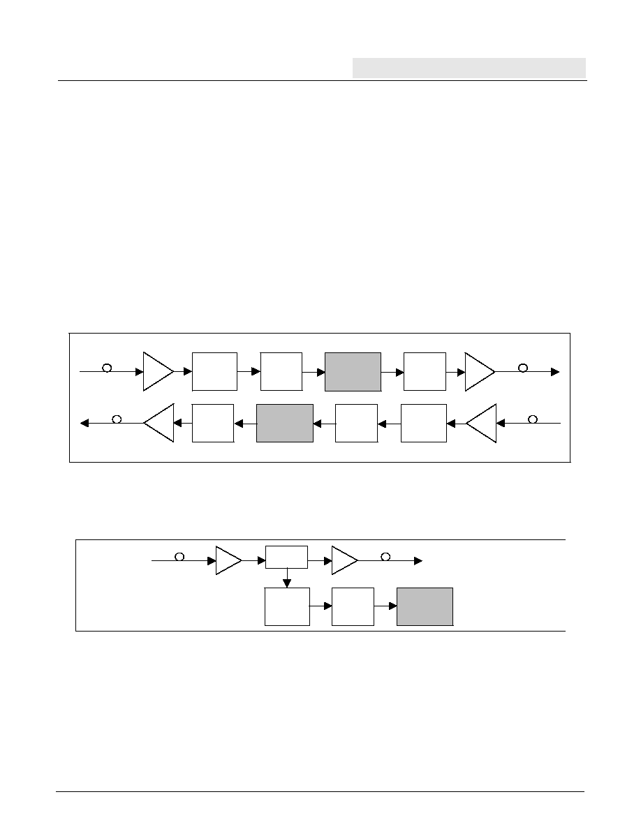
Figure 1 shows a typical network application for the Performance Monitor. Data is received from the fiber and
passed through a clock/data recovery device (CDR) and a de-multiplexer device to the S3052. The S3052, option-
ally, carries out performance monitor error checking, and overhead data extraction, and insertion. Detected errors
and accumulated error counts can be accessed by the user either through a processor interface, an FPGA inter-
face, or in a number of cases, from I/O pins. The data stream is then transmitted out onto the fiber via a high-speed
multiplexer, and an optics device. All SONET/GBE performance monitor error checking and overhead insertion
may be by-passed by selecting the low-power pass-through mode of operation.
Figure 1. Typical Monitor and Insertion Application
In Figure 2 , the S3052 is used to monitor data without overhead insertion. In this application, the MUX is removed
and a By-Pass circuit is added for a monitoring solution.
Figure 2. Typical Monitor Application
MUX
S3052
DeMUX
CDR
ORX
CDR
DeMUX
S3052
OTX
MUX
OTX
ORX
By-Pass
Circuits
ORX
CDR
DeMUX
S3052
OTX
3
S3052 ≠ Multi-Rate Performance Monitor
PRODUCT BRIEF DATA SHEET
Revision NC - Aug. 4, 1999
S3052 Applications Overview
The S3052 Performance Monitor optionally performs differential decoding and encoding on any data format. If the
data is in SONET/SDH format, the S3052 implements all required features to check the data stream and allow for
the extraction and insertion of the section and line overhead bytes. It also implements Gigabit Ethernet 8B/10B
monitoring of the data stream. The data stream may run at any frequency from 155.52 to 2500Mb/s, which includes
STS-3/STM-1, STS-12/STM-4, STS-48/STM-16 and Gigabit Ethernet rates. All use a 16-bit parallel single-ended
PECL data path that is compatible with the AMCC MUX/DeMUX chipsets. The S3052 implements SONET/SDH
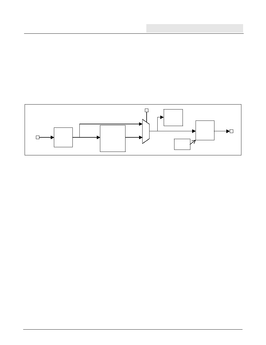
section and line overhead monitoring and insertion, and Gigabit Ethernet monitoring. The diagram in Figure 3
shows the basic building blocks of the S3052.
Figure 3. Overview Block Diagram
Pass Through Application Overview
When Pass Through mode is enabled, any data format will be passed through the S3052. All monitoring circuits
will be bypassed but differential decoding/encoding may still be enabled. Pass Through provides the lowest power
mode available from the S3052.
Gigabit Ethernet Application Overview
When Gigabit Ethernet mode is enabled, the following performance monitor functions will be running:
∑
Loss of synchronization indicators and error counts.
∑
8B/10B code violation indicators and error counts.
∑
Disparity error indicators and error counts.
Detected errors are flagged and are available to the user. Error counts are accumulated and available to the user.
SONET/SDH Generation Application Overview
For test purposes, the S3052 may generate valid SONET/SDH frames if supplied with valid input clocks. The
S3052 transmit clock will generate correct section (regenerator) overhead and line AIS even if the receive clock is
absent. If the receive clock is present, any non-random data format may be turned into SONET/SDH frame. To
complete the frame, correct section and line overhead may be inserted.
Differential
Encode
Gigabit
Ethernet
Monitoring
STS-3,12,48/
STM-1,4,16
Error
Monitoring and
Overhead
Processing
PASSTHRU or
Gigabit Ethernet
Data
In
Data
Out
Differential
Decode
Error
Injection

4
S3052 ≠ Multi-Rate Performance Monitor
PRODUCT BRIEF DATA SHEET
Revision NC - Aug. 4, 1999
SONET/SDH Application Overview
The SONET/SDH mode monitors incoming SONET/SDH data streams and optionally modifies them.
In addition to being stored in an accessible memory, received section overhead is managed as follows:
∑
A1 and A2 bytes are checked for framing and byte alignment.
∑
J0 byte is monitored for section trace messages.
∑
B1 byte is monitored and accumulates bit interleaved parity errors.
∑
E1 byte is optionally serialized and output.
∑
D1-3 bytes are optionally serialized and output.
∑
The data can be descrambled in accordance with SONET/SDH standards.
Section errors -- LOS, LOF, OOF and B1 -- are accessible.
In addition to being stored in an accessible memory, received line overhead is managed as follows:
∑
B2 byte is monitored and accumulates bit interleaved parity errors.
∑
K1 and K2 bytes are monitored for new or inconsistent values. K2 is also monitored for line AIS and RDI.
∑
D4-12 bytes are optionally serialized and output.
∑
S1 byte is monitored for inconsistent values and mismatches.
∑
M1 byte is monitored and accumulates REI errors.
∑
E2 byte is optionally serialized and output.
Line error indicators - line AIS, line RDI, line REI, B2, signal fail, signal degrade, K1, K2 and S1 changes are
accessible.
All transmitted section and line overhead bytes may be written. In addition, data transmission may be modified as
follows:
∑
Framing bytes can be regenerated with values A1 = F6h and A2 = 28h.
∑
J0 byte may be filled with section trace bytes from a memory.
∑
B1 and B2 bytes may be recalculated.
∑
E1, D1-3, D4-12 and E2 bytes can be sourced.
∑
The data can be scrambled in accordance with SONET/SDH standards.
∑
Line AIS can be activated automatically when LOS or LOF conditions are detected, or the user may force
the transmitter to output line AIS.
∑
The entire data stream can be turned OFF (all zeros output).
5
S3052 ≠ Multi-Rate Performance Monitor
PRODUCT BRIEF DATA SHEET
Revision NC - Aug. 4, 1999
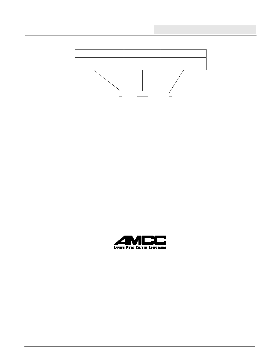
Ordering Information
Applied Micro Circuits Corporation
6290 Sequence Dr., San Diego, CA 92121
Phone: (858) 450-9333 -- (800) 755-2622 -- Fax: (858) 450-9885
http://www.amcc.com
AMCC reserves the right to make changes to its products or to discontinue any semiconductor product or service without
notice, and advises its customers to obtain the latest version of relevant information to verify, before placing orders, that the
information being relied on is current.
AMCC does not assume any liability arising out of the application or use of any product or circuit described herein, neither
does it convey any license under its patent rights nor the rights of others.
AMCC reserves the right to ship devices of higher grade in place of those of lower grade.
AMCC SEMICONDUCTOR PRODUCTS ARE NOT DESIGNED, INTENDED, AUTHORIZED, OR WARRANTED TO BE
SUITABLE FOR USE IN LIFE-SUPPORT APPLICATIONS, DEVICES OR SYSTEMS OR OTHER CRITICAL
APPLICATIONS.
AMCC is a registered trademark of Applied Micro Circuits Corporation. Copyright © 1999 Applied Micro Circuits Corporation.
Prefix
Package
Device
S ≠ Integrated Circuit
3052
TB = 352 Pin SBGA
X
XXXX
X
Prefix
Device
Package