
PRELIMINARY
This document contains information on a product under development at Advanced Micro Devices. The information
is intended to help you evaluate this product. AMD reserves the right to change or discontinue work on this proposed
product without notice.
Publication# 20975
Rev: D Amendment/+1
Issue Date: May 1998
AmMC0XXA
2, 4, or 8 Megabyte 5.0 Volt-only Flash Miniature Card
DISTINCTIVE CHARACTERISTICS
s
2, 4, or 8 Mbytes of addressable Flash memory
s
5.0 Volt-only, single power supply operation
-- Write and read voltage: 5.0 V
±
10%
-- No additional supply current required for V
PP
s
Fast access time
-- 100 or 150 ns access time
s
CMOS low power consumption
-- Typical active read current:
70 mA (word mode)
-- Typical active erase/write current:
100 mA (word mode)
-- Typical standby current:
10
µ
A (8 Mbyte card)
s
High write endurance
-- Guaranteed minimum 100,000 write/erase
cycles per card
-- More than 1,000,000 cycles per card typical
s
Uniform sector architecture
-- 64K byte individually useable sectors
-- Erase Suspend/Resume increases system level
performance
-- BUSY# and RESET# signals
s
Zero data retention power
-- No power required to retain data
s
Available in industrial temperature grade
(≠40
∞
C to +85
∞
C)
s
Miniature Card standard form factor
-- True interchangeability
-- 60-pad connector
-- Supports multiple technologies
-- Sonic welded stainless steel case
-- PCMCIA Type II adapter available
-- Selectable byte- or word-wide configuration
-- Small form factor (38 mm x 33 mm x 3.5 mm)
s
60 connection bus
-- 16-bit data bus
-- 25-bit address bus
-- Easy system integration
-- Low cost implementation
-- Low cost cards
s
Consumer-friendly mechanicals
-- User can easily insert and remove card, upgrade
memory, and add applications
s
Voltage level keying
-- Does not allow a 5 V card to plug into a 3 V
system and vice versa
-- Single power supply design
-- System does not need a separate program
voltage supply; only one is necessary to read
and write
GENERAL DESCRIPTION
The Miniature Card is an expansion card that provides
a high-performance, small form factor solution for data
and file storage to the portable, handheld market,
which includes audio, digital film, wireless, and PDA
(Portable Digital Assistant) applications. The Miniature
Card provides a low cost, low power, high performance
interface for memory cards.
Miniature cards can be easily "snapped" into the back
of an electronic system and can be readily removed
and replaced by end users. AMD's 5 V Flash Miniature
Cards are manufactured using AMD's industry leading
5.0 volt-only, single-power-supply Am29F080B and
Am29F017B Flash Memory devices, ensuring high reli-
ability and excellent performance. The Miniature Card
is less than 30% of the size of a PCMCIA memory card.
Applications include digital voice recorders, pocket
PCs and intelligent organizers, smart cellular tele-
phones, voice and data messaging pagers, digital still
cameras and portable instrumentation equipment.
The Miniature Card specification will be defined by
PCMCIA as of October 1997. The participating associ-
ation members include major Flash memory vendors
and leading consumer electronics OEMs. The goal of
the Miniature Card specification is to promote an open,
interoperable small-form-factor memory card standard.
For more information on the Miniature Card specifica-
2
AmMC0XXA
P R E L I M I N A R Y
tion, visit the PCMCIA web site at http://www.pc-
card.com.
AMD Flash Miniature Cards can be read in either a
byte-wide or word-wide mode, which allows for flexible
integration into various system platforms. Compatibility
is assured at the hardware interface and software inter-
change specification.
Miniature Card is also designed with low-cost and
rugged handling in mind. The card contains virtually
no control logic, which keeps cost and power con-
sumption to a minimum. The Miniature Card is pack-
aged in a sonic welded, stainless steel case that
guarantees durability, provides good ESD protection
and ease of handling.
The Miniature Card has extensive third-party support,
including socket and connector solutions, software
support from the major FTL software vendors, and
PCMCIA adapter solutions and programmer support.
AMD's Miniature Flash cards can be used for both code
and data storage. Since fast random access is possible,
code can be directly executed from the card, reducing
the amount of system RAM required. In addition. AMD's
Flash technology offers unsurpassed endurance, data
retention and reliability, eliminating the need for
complex error correction and defect management hard-
ware and software. Each Flash sector provides a
minimum of 100,000 cycles, which translates into a
typical card life of one million or more cycles.
For more information, please contact your local AMD
s a l e s o f f i c e o r v i s i t o u r W e b s i t e a t
http://www.amd.com/html/products/nvd/nvd.html.
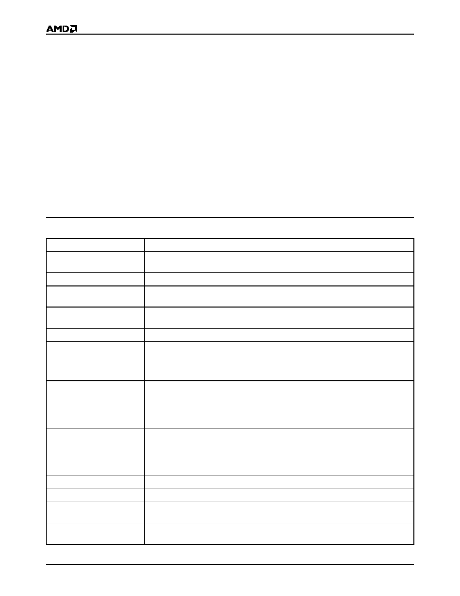
DEFINITIONS
Table 1 lists the terms and definitions that may be used
in conjunction with Miniature Card specifications.
Table 1.
Miniature Card Definitions
Term
Meaning
AIS
Acronym for Attribute Information Structure. AIS is a Miniature Card specification for storing
Miniature Card attribute information.
ESD
Acronym for Electrostatic Discharge. ESD is part of the Miniature Card physical test.
FAT
Acronym for File Allocation Table. Using an FAT is a common method for managing files in a
DOS-based system.
Flash
A type of non-volatile memory that is both readable and writeable, but requires the media to
be erased before it is rewritten.
Host
Any system that incorporates a Miniature Card socket.
Insertion, Cold
User Perception:
Insertion of the Miniature Card when the host is off.
Host State:
The host would be either off or in sleep mode, no bus activity is occurring, the
host is non-operational by the user. The user inserts the Miniature Card and then presses a
button to turn the host on before the system is operational.
Insertion, Hot
User Perception:
Insertion of a Miniature Card when the host is running.
Host State:
The host would be in running mode, bus activity is occurring, the host is
operational by the user. The user inserts the card, the host recognizes it, and the host
continues to be operational. Note: Hot insertion may require buffering on the host system for
proper operation.
Insertion, Pseudo Hot
User Perception:
Insertion of a Miniature Card when the host is running.
Host State:
The host would be in running mode, bus activity is occurring, the host is
operational by the user. The user inserts the card, the host immediately powers off before the
Miniature Card makes contact with the host's internal bus. The user would then need to press
a button to turn the host on for it to become operational.
Interface Signals
Miniature Card signals that make connection through the 60-pad connector area.
JEDEC
Acronym for Joint Electronic Device Engineering Council.
Miniature Card Backside
The side of the Miniature Card that contains the latching mechanism. The backside is
opposite the frontside.
Miniature Card Bottomside
The side of the Miniature Card that contains the interface signals. The bottomside is opposite
the topside.

AmMC0XXA
3
P R E L I M I N A R Y
Miniature Card Frontside
The side of the Miniature Card that contains power, insertion, ground, voltage keys, and
alignment notch. The frontside is opposite the backside.
Miniature Card Topside
The side of the Miniature Card that contains the Miniature Card label. The topside is opposite
the bottomside.
PC Card
A memory or I/O card compatible with the PC Card Standard.
PC Card Adapter
The hardware that connects the Miniature Card 60 contact bus to the PC Card 68 pin bus.
This hardware can be mechanically implemented by following the PC Card Type II
specification.
Power/Insertion Signals
The three signals on the frontside of the Miniature Card that provide ground, power and early
detection of insertion.
Pull-Ups
Resistors used to ensure that signals do not float when no device is driving them.
Removal, Cold
User Perception:
Removal of a Miniature Card when the host is off.
Host State:
The host would either be off or in sleep mode, no bus activity is occurring, the
host is non-operational by the user. User would turn off the host, then remove the Miniature
Card and then press a button to turn the host on for it to become operational again.
Removal, Hot
User Perception:
Removal of the Miniature Card when the host is running.
Host State:
The host would be in running mode, bus activity is occurring, the host is
operational by the user. User removes the card, the host recognizes the event, and the host
continues to be operational.
Removal, Pseudo Hot
User Perception:
Removal of the Miniature Card when the host is running.
Host State:
The host would be in running mode, bus activity is occurring, the host is
operational by the user. User removes the card, the host recognizes the event, the host
immediately powers off before the Miniature Card removes contact with the host's internal
bus. The user would then need to press a button to turn the host on for it to be operational
again.
Sector
Usually 64 Kbytes, but depends on device used in the card. In word mode, a sector is 64
KWords.
Tuple
An element of the PC Card Standard CIS that provides card attribute information, and a link
to the next tuple in a string of tuples.
User Insertable
All Miniature Cards should be inserted into the host by the user without the need for any
special tools.
User Removable
This type of Miniature Card can be removed by the user without the need for any special tools.
It contains programs and data that users may want to switch often. The use of this type of
card is similar to a floppy disk.
User Non-Removable
This type of Miniature Card must be removed by the user with a special tool. It contains
memory upgrades or boot program that users switches only when they require an upgrade.
The use of this type of card is similar to a SIMM memory expansion or boot hard disk.
XIP
Acronym for eXecute-In-Place, which refers to code that executes directly from a Miniature
Card.
Table 1.
Miniature Card Definitions (Continued)
Term
Meaning

4
AmMC0XXA
P R E L I M I N A R Y
Figure 1.
Miniature Card Connector (Card Bottom View)
Note: Refer to the Physical Dimensions section for more information. Also refer to the MCIF specification for detailed mechanical
information, available on the Web at http://www.mcif.org.
Table 2.
AMD Flash Miniature Cards and Flash Devices
Family Part Number
Density
No. of Flash Devices
AMD Flash Memory
AmMC002AWP
2 Mbyte
2
Am29F080B
AmMC004AWP
4 Mbyte
2
Am29F017B
AmMC008AWP
8 Mbyte
4
Am29F017B
Write Protect Switch (optional)
Pad 60
Pad 31
Pad 30
Pad 1
V
CC
CINS#
GND
3V/5V
Key
Alignment
Notch
20975D-1

AmMC0XXA
5
P R E L I M I N A R Y
BLOCK DIAGRAM
*
Decoder used on 8 Mbyte card only. Not used on 2 and 4 Mbyte cards.
** 2 Mbyte card: Two Am29F080B devices, S0 and S1
4 Mbyte card: Two Am29F017B devices, S0 and S1
8 Mbyte card: Four Am29F017B devices, S0...S3
*** A0≠A19 on 2 Mbyte card; A0≠A20 on 4 and 8 Mbyte cards.
Note: On the 2 Mbyte card, A20≠A24 are not connected. On the 4 Mbyte cards, A21≠A24 are not connected. On the 8 Mbyte
cards, A22-A24 are not connected. Connections not shown in this diagram are not connected internally.
OE#
BUSY#
RY/BY#
A0≠A24
Decoder*
CEL#
100K
100K
CEH#
WE#
WE# to all Flash devices
Write Protect
Switch
CEL0#
CEH0#
CEL1#
CEH1#
A21
V
CC
10K
V
CC
V
CC
OE# to all Flash devices
D0≠D7
D8≠D15
RESET#
RESET# to all Flash devices
A0-A20***
WE#
OE#
D8-D15
V
SS
V
CC
RESET# RY/BY#
S1**
A0-A20***
CE#
WE#
OE#
D0-D7
V
SS
V
CC
RESET# RY/BY#
S2**
A0-A20***
CE#
WE#
OE#
D8-D15
V
SS
V
CC
RESET# RY/BY#
S3**
A0-A20***
CE#
WE#
OE#
D0-D7
V
SS
V
CC
RESET# RY/BY#
S0**
V
CC
10K
V
CC
10K
20975D-2