Analog Microelectronics, Inc.
1
AME7700/AME7701/AME7702
Switched Capacitor Voltage Doublers
Preliminary
n
n
n
n
n
Features
l
Small packages: SOT-25, SOT-26
l
+1.5V to +5.5V Input Range
l
60uA Quiescent Current ( AME7700)
l
99% Conversion Efficiency
l
Output Current Exceeding 100mA
l
User Selectable Frequency ( AME7702)
n
n
n
n
n
General Description
The AME7700 series of economical, Charge-Pump
Converters efficiently double a +1.5V to +5.5V input to
+3.0V to +11V, with a working current exceeding 100mA.
Due to their simplicity, small size, and performance,
these CMOS converters have numerous applications.
For most cases, only (2) external capacitors are re-
quired, however, in some cases, a single capacitor is
acceptable. Minimum capacitance is obtained with the
AME7701, while the AME7700 offers the lowest stand-
by current. The AME7702 has a Frequency-Select pin
for added flexibility. The input voltage can be tripled or
quadrupled by cascading 2 Charge-Pumps. A single
alkaline battery
With it's low start-up voltage, a single alkaline battery
can be configured with (2) AME7700's to quadruple the
voltage and produce 5V out. Alternately, with a 5V
source, (2) AME7700's can be configured to triple the
voltage and produce 15V out.
n
n
n
n
n
Applications
l
Cellular Phones
l
Digital Cameras
l
Battery Chargers
l
High Tech Flashlights
l
PDA's - LCD displays
l
Consumer Electronics
l
Pagers
n
n
n
n
n
Pin Configuration
l
Portable Electronics
4
5
1
2
3
A M E 7 7 0 0
A M E 7 7 0 1
n
n
n
n
n
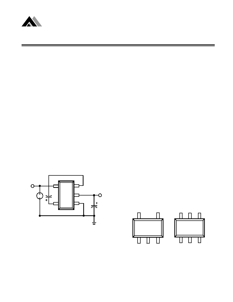
Typical Connection
4
5
1
2
3
6
AME7702
AME 7700/7701
SOT-25 Top View SOT-26 Top View
1: GND
4: IN
1: GND
4: IN
2: OUT
5: CP
2: CN
5: FC
3: CN
3: OUT
6: CP
V
O U T
V
I N
D C
O U T
C N
G N D
IN
C P
C 1
C 2
Analog Microelectronics, Inc.
2
AME7700/AME7701/AME7702
Switch Capacitor Voltage Doublers
Preliminary
n
n
n
n
n
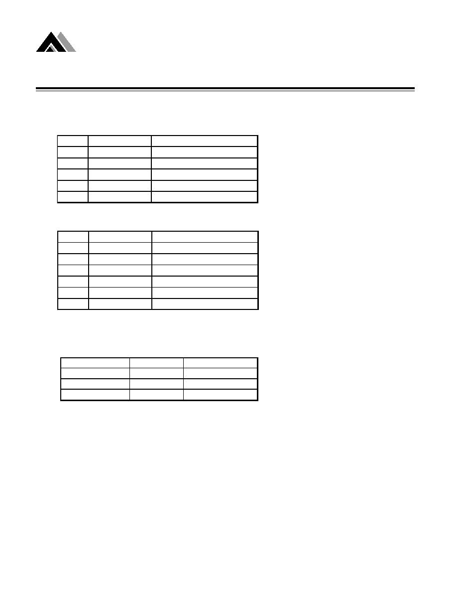
Order Information
n
n
n
n
n
Pin Description
AME7700AEEV/ AME7701AEEV
AME7702AEEY
Pin
Designation
Function
1
GND
Ground (-Supply)
2
OUT
Power Output
3
CN
Capacitor (-)
4
IN
Power Input
5
CP
Capacitor (+)
Pin
Designation
Function
1
GND
Ground (-Supply)
2
CN
Capacitor(-)
3
OUT
Power Output
4
IN
Power Input
5
FC
Frequency Control
6
CP
Capacitor (+)
Part Number
Package
Operating Temp.
AME7700AEEV
SOT-25
-40
O
C to +85
O
C
AME7701AEEV
SOT-25
-40
O
C to +85
O
C
AME7702AEEY
SOT-26
-40
O
C to +85
O
C

Analog Microelectronics, Inc.
3
AME7700/AME7701/AME7702
Switched Capacitor Voltage Doublers
Preliminary
n
n
n
n
n
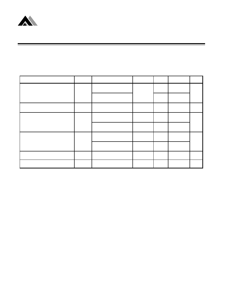
Absolute Maximum Ratings
n
n
n
n
n
Recommended Operating Conditions
n
n
n
n
n
Thermal Information
M a x im u m
U n it
6
V
B
P a ra m e te r
S up p ly V o lta g e
E S D C la s s ific a tio n
Rating
1.5 - 5.5 V
-40 to +85
o
C
-40 to +125
o
C
Ambient Temperature Range
Junction Temperature
Supply Voltage
Parameter
Maximum
Unit
250
o
C
/
W
150
o
C
300
o
C
Caution: Stress above the listed absolute rating may cause permanent damage to the device
Thermal Resistance (SOT-25,26)
Maximum Lead Temperature ( 10 Sec)
Maximum Junction Temperature
Parameter
Analog Microelectronics, Inc.
4
AME7700/AME7701/AME7702
Switch Capacitor Voltage Doublers
Preliminary
T
A
= 25 C, V
IN
= 5V unless otherw ise noted,C
1
= C
2
= 3.3
µ
µ
µ
µ
F
60
100
215
300
Supply Voltage Range
V
IN
1.5
5.5
V
8.5
12
15.5
24.5
35
45.5
40
50
20
35
Voltage Conversion Efficiency
V
EFF
97
99
%
Power Efficiency
P
EFF
88
92
%
No Load Current
I
IN
TEST CONDITIONS
PARAMETER
SYMBOL
AME7700
AME7702 FC is LO
AME7701
AME7702 FC is HI
Oscillator Frequency
F
OSC
Output Resistance
Ro
No load
R
L
= 10 K
ohms
KHz
AME7700
AME7702 FC is LO
AME7701
AME7702 FC is HI
AME7700
AME7702 FC is LO
AME7701
AME7702 FC is HI
µ
A
UNITS
R
L
= 10 K
MIN
TYP
MAX
n
n
n
n
Electrical Specification

Analog Microelectronics, Inc.
5
AME7700/AME7701/AME7702
Switched Capacitor Voltage Doublers
Preliminary
0
2
4
6
8
10
12
0
50
100
150
Load Regulation
V
OUT
I ( mA)
0
2
4
6
8
10
12
0
50
100
150
L o a d R e g
I ( m A )
V
OUT
V i n = 5
V i n = 3 . 3
V i n = 2
0
20
40
60
80
100
120
140
160
25
50
75
100
125
150
Electrical Characteristics vs. Temp
R
OUT
/
I
DD
Temperature(
0
C )
A M E 7 7 0 0
A M E 7 7 0 1
I
D D
R
O U T
A M E 7 7 0 0
0
5
10
15
20
25
30
35
1
2
3
4
5
6
Input Voltage (V)
Oscillator Frequency (KHZ)
A M E 7 7 0 1
A M E 7 7 0 0
Osc. Freq. @ 25C
2 . 2
µ
F
3 . 3
µ
F
25
30
35
40
45
50
2
3
4
5
6
Input Voltage (V)
Output Resistance (Ohm)
2 . 2
µ
F
3 . 3
µ
F
A M E 7 7 0 0 O u t p u t R e s i s t a n c e @ 2 5 C
Supply Current @ 25C
A M E 7 7 0 1
A M E 7 7 0 0
0
50
100
150
200
250
300
1
2
3
4
5
6
Input V oltage (V )
Supply Current(mA)
A M E 7 7 0 1
A M E 7 7 0 0