A132000
ADPCM SOUND CONTROLLER
Preliminary
PRELIMINARY
(December, 1999, Version 0.0)
1
AMIC Technology, Inc.
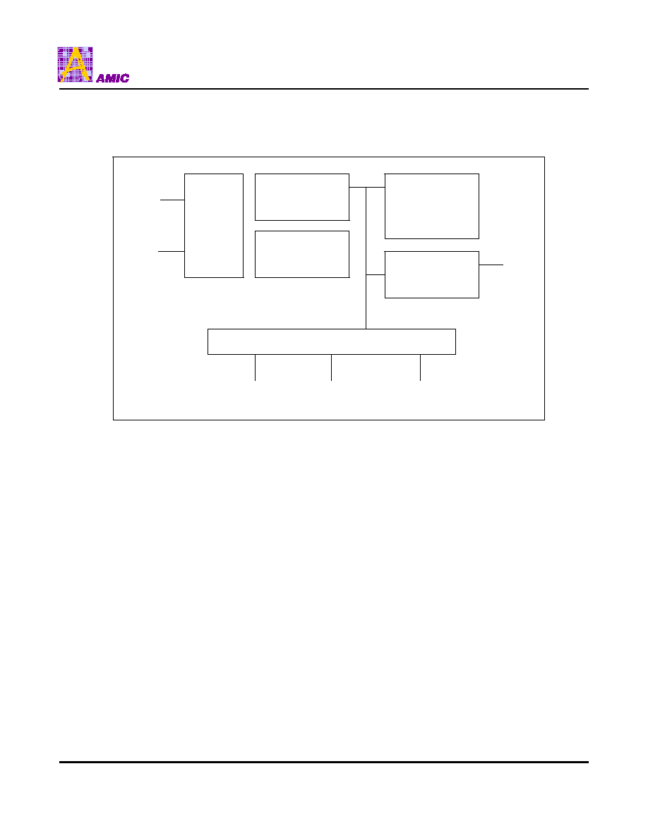
General Description
The A132000 is a fully CMOS integrated circuit. It uses advanced design and process technology to combine an 8-bit
RISC processor with program/data ROM, 80-byte working SRAM
,
timer/counter, I/O, built-in oscillator and audio current
mode D/A. The high speed RISC processor can implement software based audio processing
,
data compression
,
LCD
display, functional control and others.
Features
n
8-bit RISC controller
n
Wide operation range:2.7V-5.5V
n
Provide 2Mbit ROM area
n
Software audio for speech and melody
n
Provide maximum 2K bytes ROM area for
program data
n
Provide 60 seconds playing of audio or speech
voice
n
80bytes working SRAM
n
Built-in watch dog timer
n
Audio output, audio output current: 5 mA
n
Clock stop mode
n
8-bit timer/counters with 8-bit programmable
prescaler
n
ADPCM encoding/decoding method
n
Power-On Reset (POR)
n
Provide 8-bit current output D/A
n
Provide 20 general I/Os
n
Provide 4 output only drive LEDs
n
Key wake up function
n
Low voltage reset function
n
Crystal Operation or Built-in 4M Hz
RC-Oscillator Operation
n
ESD, insensitive
n
Two-level hardware push/pop stack
n
Only 33 single word instruction to learn
Application Field
n
Intelligent education toys
ex. Pattern to voice (animal, car, color etc.)
n
Spelling (A,B,C or Chinese)
n
Math game
n
High-end toy controller
n
Talking instrument controller
n
General speech synthesizer
n
Industrial controller
Package Type
n
n
Dice Form
A132000
PRELIMINARY
(December, 1999, Version 0.0)
3
AMIC Technology, Inc.
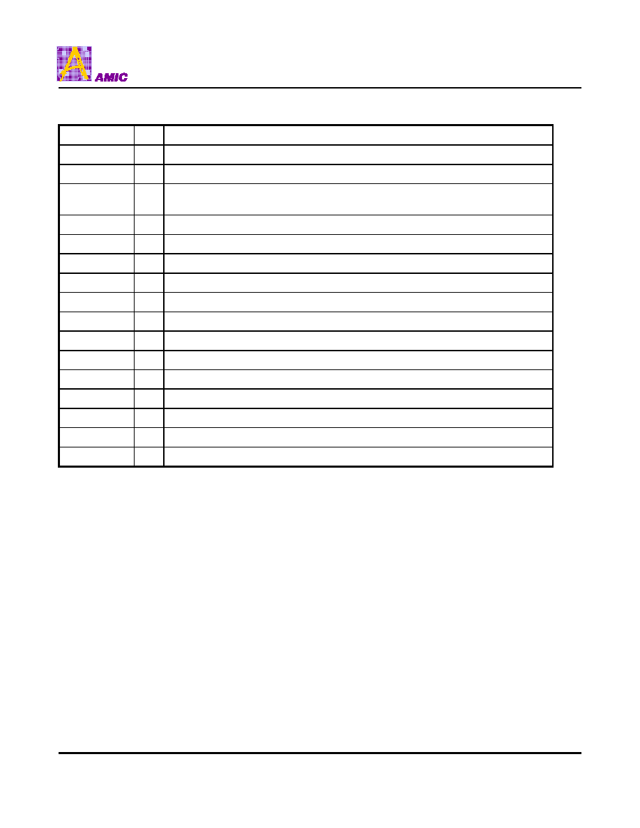
Pin Description
Symbol
I/O
Function
VCC
I
Positive Power Supply
VSS
I
Negative Power Supply
OSC1/CLKIN
I
Oscillator Crystal Input / External Clock Source Input (Crystal Mode) / External
resister Input (RC Mode).
OSC2/CLKOUT
I
Oscillator Crystal Output.
T0CKI
I
Clock Input to Timer0. Must tied to VSS or VCC if not in use
MCLRB
I
Master Clear Input. The pin active low reset to the device
RA0 ~ RA3
I/O Bi-directional I/O port, Wakeup (Pad Option)
RB0 ~ RB7
I/O Bi-directional I/O port
RC0 ~ RC7
I/O
Bi-directional I/O port
AUDA
O
Audio output
OPRA0 ~ OPRA3
I
For RA0 ~ RA3 Wakeup Enable Option / Default = 1 (Enable)
CLKOP
I
1: ( RC-OSC Mode) 0: ( XTAL Mode ) / Default = 1 (RC-OSC Mode)
TESTB
I
Reserved for Testing Mode
TSIN
I
Reserved for Testing Mode
TSOUT
O
Reserved for Testing Mode
TS1~TS0
I
Reserved for Testing Mode