
1
A64S06161A
(March, 2005, Version 0.0)
AMIC Technology, Corp.
Preliminary
Revision history
Rev. No.
History
Issue Date
0.0
Initial issue
March 28, 2005
Document Title
16M(1M x 16bit) Normal mode & Page mode Static Random Access Memory
Remark
Preliminary

2
A64S06161A
(March, 2005, Version 0.0)
AMIC Technology, Corp.
Preliminary
MEMORY
16M(1M x 16bit) Normal mode & Page mode Static Random
Access Memory
DESCRIPTION
FEATURES
� Standard Asynchronous SRAM Interface and Page Mode
� Organization
: 1M x 16Bit
� Power Supply Voltage
: 2.7 ~ 3.3 V
� Page Size
: 4 words
� Page Mode Access (tPAA)
: 35ns
� Data Retention Voltage
: 2.4V
� Tri-state Output and TTL Compatible
FUNCTIONAL BLOCK DIAGRAM
PRODUCT FAMILY
The A64S06161A is a 16Mb high speed, low power Static Random Access Memory(SRAM)
organized as 1,048,576 words by 16 bits and supports Page Mode.
The A64S06161A is a Pseudo SRAM based on successfully proven DRAM CELL SRAM which
was specifically developed for cost sensitive, low power computing and communication
applications such as mobile cellular phone handsets, personal digital assistants and other
battery-operated consumer products.
Memory Array
8192 rows
128 x 16 columns
R
o
w
D
e
c
oder
Add.
Input
Bu
f
f
er
Column Decoder
Add.
Input
Bu
f
f
er
Row
Address
Column
Address
Ref. Cont.
DC Generator Circuit
Control Logic
/CS /OE /WE
Sense Amp
.
Wr
i
t
e
D
r
i
v
e
r
D
a
t
a
I/O B
u
ff
e
r
IO0
IO7
IO8
IO15
/UB /LB
Data Input / Output
IO0
IO15
Lower Byte (IO0
7)
/LB
Address Input
A0
A19
Upper Byte (IO8
15)
/UB
Write Enable Input
/WE
Ground
VSS
Output Enable Input
/OE
Power
VCC
Chip Select Input
/CS
Name
Function
Function
Name
/PD
IO0
IO2
VCC
VSS
IO6
IO7
NC
A2
/CS
IO1
IO3
IO4
IO5
/WE
A11
A1
A4
A6
A7
A16
A15
A13
A10
A0
A3
A5
A17
VSS
A14
A12
A9
/OE
/UB
IO10
IO11
IO12
IO13
A19
A8
/LB
IO8
IO9
VSS
VCC
IO14
IO15
A18
6
5
4
3
2
1
A
B
C
D
E
F
G
H
PIN DESCRIPTION
100uA
IccDR
(Max)
100uA
ISB1
(Max)
2.0mA
ICC1
(Max)
-40 ~ 85
Operating
Temperature
70
Speed
2.7 ~ 3.3 V
Voltage
Mode
Product Family
A64S06161A
Page
Note : E3 pin ( VSS) can be remain as a NC
3
A64S06161A
(March, 2005, Version 0.0)
AMIC Technology, Corp.
Preliminary
ABSOLUTE MAXIMUM RATING
Note :
Stresses greater than those listed under "ABSOLUTE MAXIMUM RATINGS" may cause permanent
damage to the device. This is stress rating only and the functional operation of the device under these or
any other conditions above those indicated in the operation of this specification is not implied.
Exposure to the absolute maximum rating conditions for extended period may affect reliability.
PRODUCT LIST
-40 ~ 85
T
A
Operating Temperature (Extended)
-55 to 150
T
STG
Storage temperature
W
1.0
P
D
Power Dissipation
V
-0.2 to 3.6
V
CC
Voltage on Vcc supply relative to Vss
V
-0.2 to VCC+0.3 V
V
IN
, V
OUT
Voltage on any pin relative to Vss
Unit
Ratings
Symbol
Item
Standby
Deselected
High-Z
High-Z
X
X
X
X
H
H
Standby
Deselected
High-Z
High-Z
H
H
X
X
H
X
Active
Output Disabled
High-Z
High-Z
X
L
H
H
H
L
Active
Output Disabled
High-Z
High-Z
L
X
H
H
H
L
Active
Lower Byte Read
High-Z
Data Out
H
L
H
L
H
L
Active
Upper Byte Read
Data Out
High-Z
L
H
H
L
H
L
Active
Word Read
Data Out
Data Out
L
L
H
L
H
L
Active
Lower Byte Write
High-Z
Data In
H
L
L
X
H
L
Active
Upper Byte Write
Data In
High-Z
L
H
L
X
H
L
Active
Word Write
Data In
Data In
L
L
L
X
H
L
I/O 0~7
/PD
/WE
/OE
/UB
/LB
I/O 8~15
Power
MODE
/CS
TRUTH TABLE
16M, 48-FBGA , 70 ns, 3.0V, -40
85
A64S06161A-70U
Function
Part Name

4
A64S06161A
(March, 2005, Version 0.0)
AMIC Technology, Corp.
Preliminary
DC AND OPERATING CHARACTERISTICS
RECOMMENDED DC OPERATING CONDITIONS
1)
Note :
1.T
A
= -40
to 85
, otherwise specified.
2. Overshoot : Vcc + 1.0V in case of pulse width
20 ns.
3. Undershoot : -1.0V in case of pulse width
20 ns.
4. Overshoot and undershoot are sampled, not 100% tested.
5. Stable power supply required 100 us before device operation.
CAPACITANCE
(T
A
= 25
, f = 1.0MHz)
Note : This parameter is sampled and not 100% tested
pF
10
V
IO
=0V
Output Capacitance
C
OUT
pF
8
V
IN
=0V
Input Capacitance
C
IN
Unit
Max.
Condition
Parameter
Symbol
mA
20
Cycle time=Min, IIO=0mA, 100% duty
/CS = V
IL
,V
IN
=V
IL
or V
IH
Icc2
uA
100
/CS
Vcc-0.2V, /UB=/LB
Vcc-0.2V
(/UB,/LB Controlled) Other inputs = 0 or Vcc
I
SB1
Standby Current(CMOS)
mA
10
/CS1 = V
IL
, CS2=V
IH
,Tpwc = min Page
address cycling
Iccp
mA
2.0
Cycle Time = 1 us, 100%duty, I
IO
=0mA,
/CS
0.2V, V
IN
0.2V or
V
IN
Vcc-0.2V
Icc1
V
2.2
I
OH
= -1 mA
V
OH
Output High Voltage
V
0.4
I
OL
= 2 mA
V
OL
Output Low Voltage
mA
0.3
/CS=V
IH
, /UB=/LB= V
IH,
Other inputs = V
IH
or
V
IL
I
SB
Standby Current(TTL)
uA
1
-1
/CS = V
IH
, /UB=/LB= V
IH
or /OE=V
IH
or
/WE=V
IL
, V
IO
=Vss to Vcc
I
LO
Output Leakage Current
uA
1
-1
V
IN
= Vss to Vcc
I
LI
Input Leakage Current
Unit
Max
Typ
Min
Test Condition
Symbol
Parameter
0.4
Vcc+0.2
2)
0
3.3
Max
V
-
-0.2
3)
V
IL
Input Low Voltage
V
-
0.8*Vcc
V
IH
Input High Voltage
V
0
0
Vss
Ground
V
3.0
2.7
Vcc
Supply Voltage
(5)
Unit
Typ
Min
Symbol
Parameter

5
A64S06161A
(March, 2005, Version 0.0)
AMIC Technology, Corp.
Preliminary
Data Retention Electric Characteristic
T
A
= -40
to 85
(Normal), unless otherwise specified
-
-
Typ.
(1)
tRC
0
2.4
Min
Refer to data retention wave
form
Vcc=2.4V,
/CS=/PD=V
IH
Vcc-0.2V or
/UB,/LBVcc-0.2V,
V
IN
V
CC
-0.2V or
V
IN
V
SS
+ 0.2V
/CS=/PD=V
IH
Vcc-0.2V or
/UB,/LBVcc-0.2V,
VI
N
V
CC
-0.2V or
V
IN
V
SS
+ 0.2V
Test Condition
-
-
100
3.3
Max
t
R
t
CDR
Icc
DR
V
DR
Symbol
ns
Operating Recovery
Time
ns
Chip Deselect to Data
Retention Time
uA
Data Retention
Current
V
Voltage for Data
Retention
Unit
Item
(1) V
cc
= 2.4V,
T
A
= 25
Data Retention Wave Form
V
CC
2.7V
VI
H
V
DR
V
SS
Data Retention Mode
/CS
Vcc-0.2V
t
CDR
t
R
/CS

6
A64S06161A
(March, 2005, Version 0.0)
AMIC Technology, Corp.
Preliminary
AC TEST CONDITIONS
T
A
= -40
to 85
(Normal), unless otherwise specified
AC TEST LOADS
Note : (1) Including jig and scope capacitance
TTL
CL
(1)
CL = 30pF + 1TTL Load
Output Load
1.5V
Input and Output Timing Reference Level
5ns
Input Rise and Fall Time
0.4V to 2.2V
Input Pulse Level
Value
PARAMETER
POWER UP TIME
At starting, maintain stable power for a minimum 100us with /CS = /PD = high.

7
A64S06161A
(March, 2005, Version 0.0)
AMIC Technology, Corp.
Preliminary
Unit
70ns
Symbol
Parameter List
ns
0
tAS
Address Set-up Time
ns
10
tP
Page Write Precharge Time
ns
35
tPWC
Page Write Cycle Time
ns
5
tOW
End of Write to Output Low-Z
ns
20
tPDW
Page Write Data to Write Time overlap
ns
10
tP
Page Read Precharge Time
ns
10
tOH
Output Hold from Address Change
ns
35
tPRC
Page Read Cycle Time
ns
35
tPAA
Page Read Address Access Time
ns
25
0
tOHZ
Output Disable to High-Z Output
ns
25
0
tBHZ
/UB, /LB Disable to High-Z Output
ns
25
0
tHZ
Chip Disable to High-Z Output
ns
5
tOLZ
Output Enable to Low-Z Output
ns
10
tBLZ
/UB, /LB Enable to Low-Z Output
ns
10
tLZ
Chip select to Low-Z Output
ns
70
tBA
/UB,/LB Access Time
ns
35
tOE
Output Enable to Valid Output
ns
70
tCO
Chip Select to Output
ns
70
tAA
Address Access Time
ns
70
tRC
Read Cycle Time
R
E
A
D
ns
60
tAW
Address Valid to End of Write
ns
0
tWR
Write Recovery Time
ns
50
tWP
Write Pulse Width
ns
60
tBW
/UB, /LB Valid to End of Write
ns
60
tCW
Chip Select to End of Write
ns
70
tWC
Write Cycle Time
W
R
I
T
E
ns
0
tPDH
Page Write Data Hold from Write Time
ns
0
tDH
Data Hold from Write Time
ns
40
tDW
Data to Write Time Overlap
ns
20
0
tWHZ
Write to Output High-Z
Max
Min
AC CHARACTERISTICS
(Vcc = 2.7 ~ 3.3V, T
A
= -40 to 85
)

8
A64S06161A
(March, 2005, Version 0.0)
AMIC Technology, Corp.
Preliminary
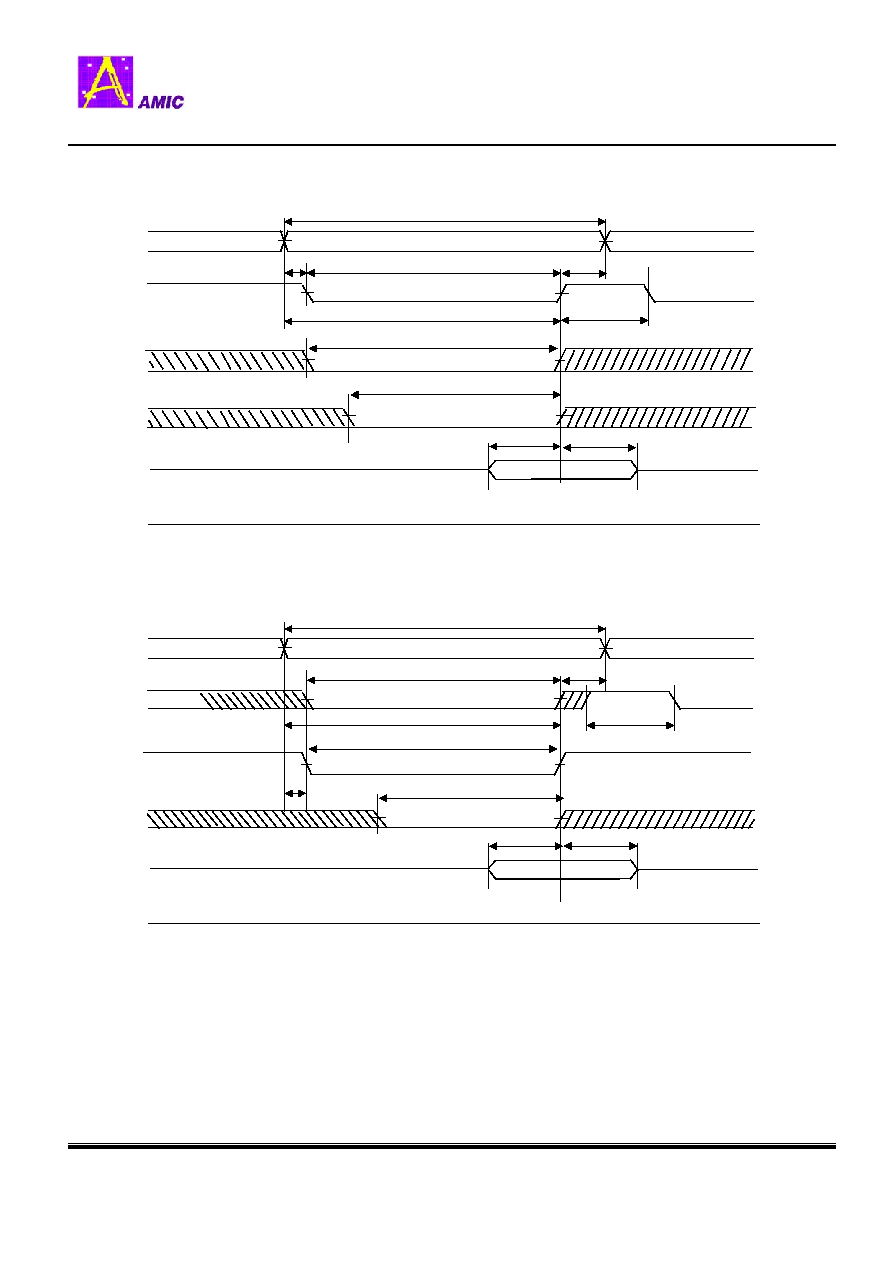
READ CYCLE
(/PD = /WE = V
IH
)
Note (READ CYCLE) :
1. tHZ and tOHZ are defined as the time at which the outputs achieve the open circuit conditions and are
not referenced to output voltage levels
2. At any given temperature and voltage condition, tHZ(max.) is less than tLZ(min.) both for a given
device and from device to device.
3. /WE is high for the read cycle.
4. Do not access device with cycle timing shorter than tRC for continuous periods > 16us.
TIMING DIAGRAMS
tRC
tAA
tCO
tBA
tOE
tHZ(1,2)
tOHZ(1)
Address(A2 � A19)
Page Address(A0 � A1)
/CS
/UB,/LB
/OE
DATA OUT
tP
tLZ(2)
tAS

9
A64S06161A
(March, 2005, Version 0.0)
AMIC Technology, Corp.
Preliminary
PAGE READ CYCLE
(/PD = /WE = V
IH
)
Note (PAGE MODE READ CYCLE) :
1. tHZ and tOHZ are defined as the time at which the outputs achieve the open circuit conditions and are
not referenced to output voltage levels
2. At any given temperature and voltage condition, tHZ(max.) is less than tLZ(min.) both for a given
device and from device to device.
3. /WE is high for the read cycle.
4. Do not access device with cycle timing shorter than tRC for continuous periods > 16us.
5. tP (precharge time) should be guaranteed for new Address.
6. After initial page access is accomplished, the page mode operation provides fast read access speed of
random locations within that page
tRC
tAA
tCO
tBA
tOE
tHZ(1,2)
tOHZ(1)
Address (A2-A19)
Page Corresponding (A0-A1)
Addresses
/CS
/UB,/LB
/OE
DATA OUT
tPRC
tPAA
tP(5)
tLZ(2)
tAS
10
A64S06161A
(March, 2005, Version 0.0)
AMIC Technology, Corp.
Preliminary
WRITE CYCLE 1
(/CS Controlled, /PD = V
IH
)
ADDR
Data Valid
tWR
tAS
tDW
tDH
tAW
tCW
/CS
Data In
Data
Out
tBW
tWC
High-Z
High-Z
High-Z
tWP
/WE
/UB,/LB
Notes (WRITE CYCLE) :
1. A write occurs during the overlap of a low /CS and low /WE. A write begins at the latest
transition among /CS going low and /WE going low: A write end at the earliest
transition among /CS going high and /WE going high. tWP is measured from the
beginning of write to the end of write.
2. tCW is measured from the later of /CS going low to the end of write.
3. tAS is measured from the address valid to the beginning of write.
4. tWR is measured from the end of write to the address change. tWR is applied in case a write ends
as /CS.
5. Do not access device with cycle timing shorter than tRC for continuous periods > 16us.
WRITE CYCLE 2
(/UB /LB Controlled, /PD = V
IH
)
tP
ADDR
Data Valid
tWR(4)
tAS(3)
tWP
tDW
tDH
tWC
tAW
tCW(2)
/CS
/WE
Data In
Data
Out
/UB,/LB
tBW
High-Z
tP

11
A64S06161A
(March, 2005, Version 0.0)
AMIC Technology, Corp.
Preliminary
PAGE MODE WRITE CYCLE
(/PD = V
IH
)
Notes (PAGE MODE WRITE CYCLE) :
1. A write occurs during the overlap of a low /CS and low /WE.
A write begins at the latest transition among /CS going low in initial page mode .
A write end at the earliest transition among /CS going high and Page Address transition.
tWP is measured from the beginning of write to the end of write in initial page access.
2. tPWC is measured from Page Address trasition (After initial page access)
to Page Address transition or /CS going high.
2. tCW is measured from the later of /CS going low to the end of write in initial page access.
3. tAS is measured from the address valid to the beginning of write.
4. Do not access device with cycle timing shorter than tRC for continuous periods > 16us.
5. tP (precharge time) should be guaranteed for new Page Address.
6. After initial page access is accomplished, the page mode operation provides fast read access speed of
random locations within that page
tWC
tBW
tWP(1)
tPDH
Address(A2 � A19)
Page Address(A0 � A1)
/CS
/UB,/LB
/WE
DATA IN
tPWC
tP
tPDW
tCW(3)
tDH
tDW
DATA OUT
High-Z
tAS(1)
tPDH
tPDW

12
A64S06161A
(March, 2005, Version 0.0)
AMIC Technology, Corp.
Preliminary
Ordering Information
48B Pb-Free Mini BGA
20
70
A64S06161AG-70UF
48B Mini BGA
20
70
A64S06161AG-70U
48B Pb-Free Mini BGA
20
70
A64S06161AG-70F
48B Mini BGA
20
70
A64S06161AG-70
Package
Operating Current
Max. (mA)
Access Time (ns)
Part No.
�Note : -U is for -40c ~ 85c temperature grade

13
A64S06161A
(March, 2005, Version 0.0)
AMIC Technology, Corp.
Preliminary
PACKAGE DIMENSION FOR BGA TYPE
48 BALL FINE PITCH 6mm x 8mm BGA(0.75mm ball pitch)
B
E
B
#A1
C
Unit: millimeters
B1
B/2
C1
C
A1 INDEX MARK
6 5 4 3 2 1
H
G
F
E
D
C
B
A
C1 / 2
0.10
-
-
Y
0.30
0.25
0.20
E2
0.90
-
-
E1
1.20
-
-
E
0.40
0.35
0.30
D
-
5.25
-
C1
8.10
8.00
7.90
C
-
3.75
-
B1
6.10
6.00
5.90
B
-
0.75
-
A
Max
Typical
Min
D
C
E
2
E
1
Side View
Top View
Bottom View
A
Y
0
.
2
5
/
T
y
p
.
0
.
9
0
/
T
y
p
.