
Æ
OVERVIEW
The CMAX systems are high
performance microstepping positioning
control devices with integrated driver
and power supply. Models include the
CMAX-410, for general-purpose
automation requirements and the
CMAX-810 for high torque, high speed
applications. Both models are CE
certified to meet EMC and Low-voltage
Directives.
The CMAX systems communicate
through high speed RS-422 serial
protocol. A simple, single character
mnemonic command set is used for
programming. Operation is in either fixed
or variable resolution mode with step
resolution to 51,200 steps/rev. Discrete
I.O. lines include four user definable and
eight dedicated inputs, five general
purpose and one dedicated output.
The CMAX systems simplify motion
control with standard features such as
programmable motor run and hold current,
independent accelleration and
deceleration ramping and 2k bytes of non-
volatile memory for program storage.
Short circuit, over temperature and under
voltage protection, combined with special
"Watchdog" software, provide trouble-
free operation in all environments.
Encoder feedback is available for closed-
loop control.
FEATURES
∑
Integral indexer/driver/power supply
∑
CE certified for international use
∑
Output currents of 4A/40Vdc to 8A/80Vdc
(8A/160Vdc optional)
∑
1/256 (fixed or variable) motor step
resolution
∑
Programmable run/hold current
∑
RS-422 "Party Line" operation
∑
Programmable accel/decel ramps
∑
2K bytes of non-volatile memory
∑
Home/limit inputs
∑
Dual speed jog inputs
∑
Go and soft stop inputs
∑
Four buffered/filtered user input ports
∑
Five general purpose outputs
∑
Programmable trip point
∑
Encoder feedback option
∑
Short circuit, over temperature and
under voltage protected
∑
"Watchdog" software for guaranteed
reliability
EMC AND THE CE MARK
The European Union (EU) Directive
regarding Electromagnetic Compatibility (EMC)
affects "any apparatus liable to cause
electromagnetic disturbance or whose
performance is liable to be affected by
such disturbance" (Directive 89/336/EEC article
2.1). Today, all products entering the EU
fitting this description must be tested to
the standards defined by the EMC
Directive. At the end-user level,
displaying a CE (Certificate European)
Mark on the equipment indicates
compliance with the EMC Directive and
ensures access to the lucrative EU
market.
All CMAX products have undergone
extensive development and test to
comply with the EMC Directive. In
addition to the marketing advantages
associated with this process, CE
approved designs ensure maximum
power surge protection and noise
immunity for dependable operation in all
environments.
CMAX
" " CERTIFIED
HIGH PERFORMANCE
MICROSTEPPING
SYSTEMS
AC
DRIVER
MOTOR
"VRMC"
CONTROLLER
I
N
T
E
R
F
A
C
E
POWER
SUPPLY
ENCODER
FEEDBACK
INTEGRAL CONTROLLER, DRIVER, POWER SUPPLY

CMAX-410
Both CMAX models are designed for use
with 2 phase, bi-polar, permanent magnet
stepper motors. The CMAX-410 will
operate NEMA 23 and single stack 34 frame
size motors. Packaged in a compact (4 x 5 x 8
inch long), fan-cooled aluminum enclosure
it includes a programmable controller, a 4
amp per phase microstepping driver and a
40Vdc (90VA) power supply. Typical
applications include plotting, medical
instrumentation, coil winding, labeling,
scanning and metering.
CMAX-810
The CMAX-810 integrates a programmable
controller with a powerful 8 amp/phase
microstepping driver and an 80Vdc (180VA)
power supply for use with the larger 34 and
42 frame size motors. A 160Vdc option is
available for higher speed requirements.
The enclosure measures 4 x 5 x 11 inches
long. Typical applications include cutting,
welding, drilling, grinding, and packaging.
PROGRAMMABLE CURRENT
A programmable current feature controls
motor winding current to within 1%
resolution. Independent settings for "RUN"
and "HOLD" currents permit full motor
torque when stepping. Automatic power
down to the hold current value minimizes
motor power dissipation when the system is
in an idle mode of operation.
INDEPENDENT ACCEL/DECEL RAMP
The CMAX systems feature independent
acceleration and deceleration ramping for
added flexibility in generating custom
motion profiles.
The separate decelerate parameter is a
valuable time saver when compared to
systems with fixed acceleration and
deceleration times.
PROGRAMMING IN "NV" MEMORY
The CMAX hosts 2,048 bytes of non-volatile memory for storage of operational
parameters, speeds and user programs. Direct read and write commands allow host
use of the memory. Additionally, 64 bytes of internal RAM is available for "Scratch
Pad" (fast read/write) applications.
For stand-alone use there is a "GO" switch input. Additional input ports can test
and branch to multiple motion subroutines. Two high power outputs are available
to drive solid state relays and other devices. A separate "TRIP" function provides
automatic program branching when a specified motion is passed. Additional control
inputs include soft stop, dual speed jog and step by step monitoring of travel limits.
VARIABLE RESOLUTION MICROSTEP CONTROL (VRMC
Æ
)
VRMC
Æ
is an advanced technology developed by AMS that produces high
resolution microstep positioning at slow shaft speeds for silent, resonance free
operation. As shaft speed increases, the output step resolution is automatically
expanded using a technique known as "on-motor-pole" synchronization. At the
completion of a coarse index, the target micro position is trimmed to 1/100 of a step
to achieve and maintain precise positioning.
The results are an advanced microstepping controller designed to produce
accurate, repeatable positioning with minimal effort and cost.
SERIAL INTERFACE
Communication is via RS-422 protocol and may operate in either Single or Party
Line mode. The Single mode provides user friendly one axis communication for
setup and debug functions. Party Line permits multiple CMAX units to be
controlled from a single communications port.
In Party Line mode differential line drivers and receivers are used to provide reliable
communication in noisy environments. This design allows a single Master (or Host)
computer and up to 32 Slave controllers to be connected in parallel and permits full
duplex communication with all controllers "listening" simultaneously for incoming
commands.
COMMUNICATIONS
RS-422
COMMAND PROCESSOR
N/V MEMORY
PROGRAM EXECUTION
CONTROL
RAMP SPEED
LOOK-UP TABLE
SLOPE STEP TIMER
INITIAL VELOCITY
FINAL VELOCITY
UP/DN RAMP COUNTERS
SLEW COUNTER
SINE GENERATION
COSINE GENERATION
OUTPUT CONTROL
MODE SELECT
OPTO ISOLATION
I/O LIMIT SWITCHES
POWER
CHOPPER
DRIVER
FEEDBACK
VARIABLE MODULO COUNTER
STEP/N (256/128/64/32/16/8/4/2)
INITIAL
VELOCITY
V
E
L
O
C
I
T
Y
I
N
S
P
S
ACCEL 50 STEPS
AT EACH POINT
TRAVEL DISTANCE IN STEPS
SLEW VELOCITY
DECEL 5 STEPS
AT EACH POINT

COMMANDS
ESC
Abort/Terminate
@
Soft Stop
^C
Reset
A
Port Read/Write
B
Set Jog Speeds
C
Clear and Restore
c
Reset Driver
D
Divide Step Rates
E
Enable Auto Power Down
F
Find Home (SPS)
G
Go
H
Step Resolution
I
Initial Velocity (SPS)
J
Jump to Address N + 1(X) K
Ramp Slope
k
Special Trip
L
Loop on Port
l
Limit Polarity
M
Move at Constant Speed
O
Set Origin
P
Program Mode
Q
Query (List) Program
R
Index to Target Position
S
Store Parameters
T
Trip Point Set
V
Slew Velocity (SPS)
W
Wait N Milliseconds
w
Driver Status
X
Examine Parameters
Y
Hold/Run Currents
Z
Display Position
+
Index in + Direction
-
Index in - Direction
[
Read NV Memory
\
Write to NV Memory
]
Read Limits/Hardware
^
Read Moving Status
|
Selective Termination
Encoder Commands:
A
Stall Count
d
Dead-band Enable
e
Encoder Resolution
f
Find Encoder Mark
h
Hunt Resolution
n
Force Encoder Position
o
Set Origin to Zero
q
Query (List) Programs
r
Set Stall Retry Count
s
Stall Factor
t
Stall Test Data
v
Hunt Velocity
z
Read Encoder Position
ENCODER FEEDBACK
The CMAX systems support encoder feedback for use in closed-loop, positioning
applications. The following elements are used to provide this function:
∑
Input buffers (two differential input comparators with RC filters) to eliminate
noise.
∑
Digital filters to further sample and shape waveforms.
∑
A quadrature decoder to convert inputs to count/direction and multiply count by
four.
∑
A 24 bit up/down counter and latch to track encoder position.
∑
A slave processor that detects and notifies the host CPU of stall or position drift
conditions.
AUXILIARY I.O.
The 25 Pin DB style I.O. connector supports 4 general purpose inputs, 5 general
purpose outputs, 8 dedicated inputs, 1 dedicated output, and flexible user support
facilities.
WATCHDOG FUNCTIONS
The CMAX incorporates a special timer that continuously monitors the operation
of the microprocessor. If the microprocessor does not respond for some reason, the
timer will set a flag that causes an unconditional reset of the system.
A "Power Fail Interrupt" feature detects when a logic power supply voltage is out
of tolerance. During power down, or a power interruption, the processor will be held
at a reset condition until the proper voltage (5V) is restored.
FAULT PROTECTION
The CMAX is internally protected against phase to phase and phase to ground
short circuits, over temperature and under voltage. Two LEDS on the front panel
indicate operating conditions and status.
Each unit is packaged in a specially designed heat-sink with cooling fan to help
avoid over temperature conditions. Should an over temperature condition occur
however (between 60
∞
C and 70
∞
C), the driver will automatically shut down.
If the DC voltage to the driver drops below the minimum specification, the drivers
output stage will be disabled. For added safety, the driver must be reset to enable
the outputs when the proper voltage and/or temperature condition is restored.
The short circuit protection consists of phase to phase, phase to ground, and +V to
phase. If a phase short to ground fault is detected, the outputs will be disabled and
can not be re-enabled without resetting or powering down the driver.
All inputs have RC noise
filters, followed by
voltage comparators
with hysteresis, for high
noise immunity. The
input threshold voltage
is set to 50% of VIO, the
input circuit supply
voltage. VIO is supplied
from the 6 volt bias
supply via an isolation
diode. An external
supply may be used if a
higher input voltage
PORT 2 (IN)
PORT 4 (OUT)
MOVING (OUT)
PORT 5 (OUT)
PORT 3 (IN)
PORT 1 (IN)
JOG HS
GND
GO (IN)
+5 VOLT
NC
RESERVED
NC
+5 VOLT
HOME SW (IN)
LIMIT A
LIMIT B
JOG CCW (IN)
JOG CW (IN)
TRIP (OUT)
SOFT STOP
PORT 4 (IN)
VIO
GND
GND
IN SERIAL OUT
ENCODER
L2
L3
L1
L4-L5
AUXILIARY 1/0
AC INPUT
GND
POWER
DANGER! HIGH VOLTAGE
NO USER SERVICEABLE PARTS INSIDE
MOTION CONTROL SYSTEM
MOTOR
1A 1B 2A 2B
CMAX
ADVANCED MICRO SYSTEMS, INC. reserves the right to make improvements, and changes in specifications or prices at any time without prior
notification.
EASI DISKETTE
AMS provides free application development
software; featuring:
∑
Program Editor
∑
Syntax Checker Loader
∑
Microsoft "C" Source Code
∑
Pull-Down Menus
∑
Dumb Terminal Emulation
∑
Quick Basic Information Program
∑
Speed, Distance, Accel/Decel Plots
ENVIRONMENTAL SPECIFICATIONS
Storage: -45 to 85 Degrees C
Operating: 0 to 55 Degrees C
Humidity: 0 to 95% (Non-condensing)
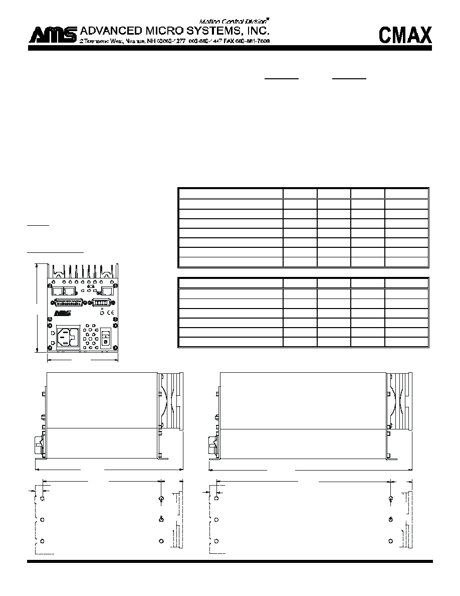
MECHANICAL SPECIFICATIONS
Weight
CMAX-410: 5.2lbs (2.4kg)
CMAX-810: 9.4lbs (4.3kg.)
Size in inches (mm)
ELECTRICAL SPECIFICATIONS
CMAX-410
CMAX-810
Power Supply................... 40Vdc (90VA)
80Vdc* (180VA)
Output Current (Peak)..... 4 Amps
8 Amps
Chopping Frequency....... 28kHz
Input Voltage................... 100 to 125 VAC; 60Hz or 200 to 250 VAC; 50Hz
Microsteps (Full Step)..... Variable, 2, 4, 8, 16, 32, 64, 128, 256
Encoder Resolution......... 50 to 12,750 Lines (in multiples of 50)
Non-Volatile Memory..... 2k Bytes
Position Counter.............. ±8,388,607
Baud Rate........................
9600 (Std.), 460k (Selectable)
*160Vdc option available. Specify at time of order.
8.12 OVERALL
(206.25)
6.50
(165.10)
4.00
(101.60)
5.00
(127.00)
1.24
(31.50)
1.25 TYP
(31.75)
11.62 OVERALL
(295.15)
10.00
(254.00)
1.24
(31.50)
1.25 TYP
(31.75)
0.38
(9.65)
MOUNTING PATTERN
I
N SERIAL OUT
E
N
C
O
D
E
R
L2
L3
L1
L4-L5
AUXILIARY 1/0
AC INPUT
G
N
D
P
O
W
E
R
DANGER! HI
GH VOLTAGE
NO USER SERVICEABLE PARTS INSIDE
MOTION CONTROL SYSTEM
M
O
T
O
R
1A 1B 2A 2B
CMAX
MOUNTING PATTERN
CMAX-410
CMAX-810
0.38
(9.65)
I.O. Signals (J3)
Min
Typ
Max
Units
I.O. Supply (VIO)
5
5.4
28
Vdc
Inputs (Ports 1,2,3,4):
Input Voltage
-0.7
VIO/2
VIO
Vdc
Input Current
500
µ
A
@
5V
Outputs (Ports 4,5,6):
Output Voltage
100
Vdc
Output Current
0.5
Amp (cont)
Control Signals
Min
Typ
Max
Units
Encoder Supply Voltage
5
Vdc
Encoder Supply Current
50
mA
Encoder Inputs
-0.7
5.7
Vdc
Encoder Input Currents
5
10
mA
RS485 Inputs
-10
+15
Vdc
RS485 Outputs
5
Vdc