SINGLE STEP
Instructions may be entered with a "Single
Instruction Execute on Strobe" attribute.
Instructions having this attribute are
delayed until a low is asserted on port 1.
This feature is valuable when implement-
ing a master/slave type system.
TRIP POINT
The trip point is a programmable position
that allows predefined operations to be
triggered when the motor position matches
the established trip point position. During
motion the position counter is continu-
ously updated and compared to the
programmed trip position.
RESET
Upon hardware reset all parameters are
initialized to factory set default values. If
non-volatile memory is present, the
parameters most recently saved are
downloaded into the working registers of
the SMC-C24. Both Jog and Go inputs are
then active. During reset all inputs and
outputs are at a high state. The communi-
cation mode is set per levels present at
Baud 1, Baud 2, and Baud 3.
NON-VOLATILE MEMORY
The SMC-C24 provides a 2k byte non-
volatile memory interface to store user
programs for future execution. Any
number of programs may coexist, limited
only by the available memory space. By
implementing NV memory, all param-
eters, such as initial velocity, ramp, full/
half step, etc., may be set as defaults or
changed "on the fly" during program
execution.
TERMINAL INTERFACE
By using a simple RS-232 buffer, a
motion sequence can be programmed
from a standard terminal or host PC.
Command lines consist of an ASCII
character followed by a number. The input
line editor provides a user friendly
interface.
SERIAL HOST DAISY CHAIN
This mode of operation connects the
SMC-C24 controllers in series with a host
computer using a single serial port. On
reset, the host issues a command to assign
each controller a unique single character
"Name" to be used as a prefix to subse-
quent commands. The host can then
obtain status and positional information at
any time.
Example: "Move 1000 Steps"
1. Non-daisy chained command:
+1000 (CR) Carriage Return
2. Daisy chained command:
A +1000 (LF) Line Feed
PARTY LINE MODE
Party Line protocol can be implemented in
systems where non-volatile memory is
available for Name storage. Each SMC-
C24 controller monitors the host and
"wakes up" on receipt of a matching
Name character.
Party Line mode is invoked by simply
supplying a low to pin 13 of the control-
ler. This protocol greatly reduces commu-
nication time and can support over 60
axes of motion, connected in parallel,
from a single serial port.
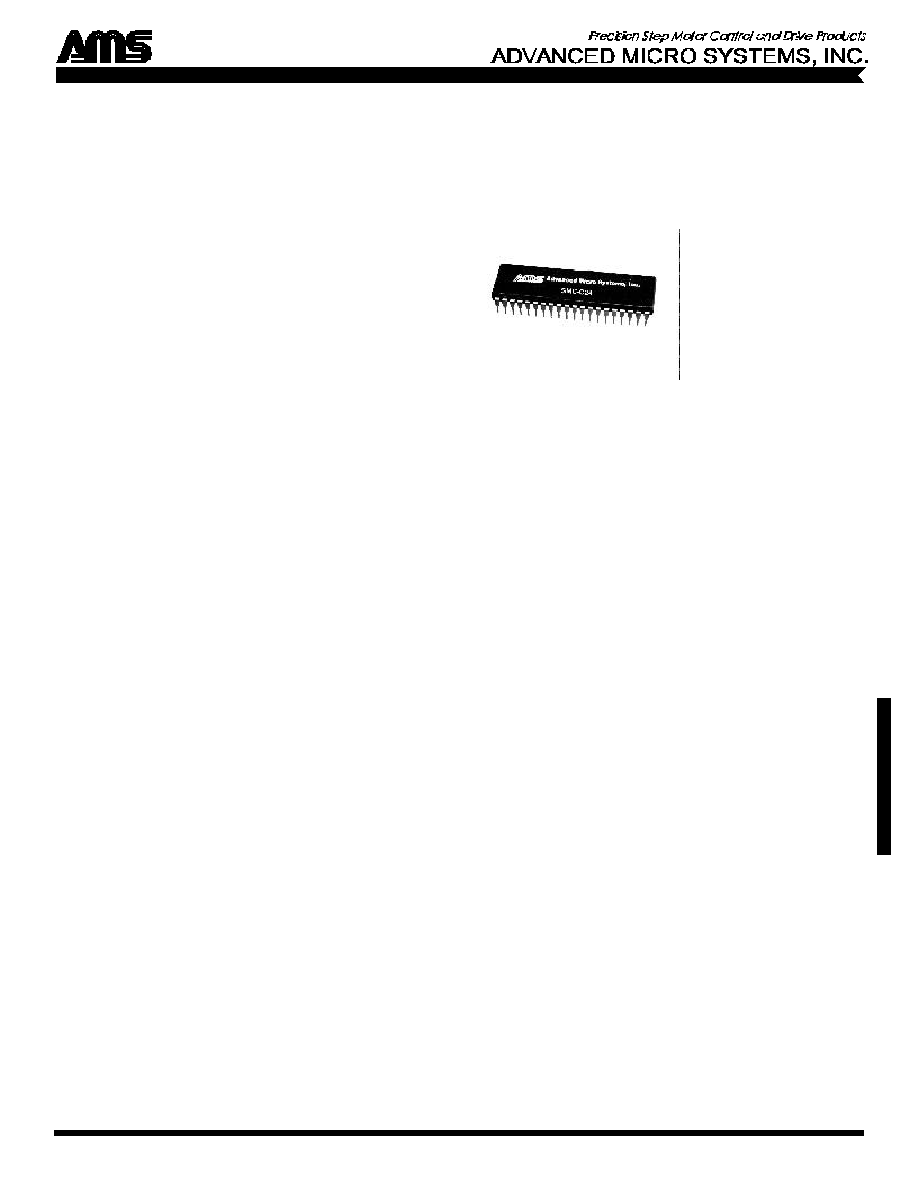
SMC-C24
HIGH PERFORMANCE
STEP MOTOR CONTROL I.C.
The SMC-C24 is a powerful, user friendly
microprocessor capable of generating all
required signals for high performance step
motor control. Features include position
trigger, loop on port or count delays, 5
user ports, limit and home sensor inputs.
High level commands, via serial line
editor or BUS, permit precise control.
Outputs include auto power down, clock,
direction and status. Inputs are available
for two speed jog and trigger. Bi-direc-
tional ramping between speeds and ramp
slope control is also supported.
The SMC-C24 has an instruction set of
over 30 sophisticated motion commands.
Other standard features include ASCII
serial port chaining up to 60 controllers,
constant velocity commands and 2k byte
non-volatile memory interface.
FEATURES
� Absolute or relative position commands
� Bi-directional ramping between speeds
� 5 general purpose input/output ports
� Speeds to 23,000 steps per second
� Speed alterable "on the fly"
� Soft decelerate stop command
� Motion output signal
� Receive/send commands while moving
� Position register of over 16M steps
� Programmable enable signal polarity
� "Home" function at any step rate
� Read position counter while moving
� Limit and home switch inputs
� 2k non-volatile memory interface
� 300 to 480k Baud selectable
� Programmable trip point
� Selectable "Party Line" serial mode
� Programmable limit switch polarity
� 16-way branch inputs
� Simple, friendly bus interface
PROGRAM DISKETTE
Installation and software development is
simplified by using the complimentary
program diskette that accompanies each
AMS motion control product. Features
include pull-down menus, Dumb Terminal
emulation, a program editor, compiler and
loader, and access to the Source Code
(Microsoft
TM
"C").
S
M
C
-
C
2
4
www.stepcontrol.com

BUS INTERFACE
The SMC-C24 controller is designed with a microcomputer interface in
mind. A simple bus interface that includes address decoding, data
buffering and handshake (for multiple axes of control) can be config-
ured by implemented a few additional components.
The binary command length is variable, depending on the specific
command. Commands in bus mode are entered as a binary sequence, as
follows:
Low
Mid
High
Command
Byte
Byte
Byte
4 Byte
17h
E8h
03h
00h (Move +1000 steps)
2 Byte
05h
00h
(Disable motor current)
2 Byte
05h
01h
(Enable motor current)
SIGNED NUMBERS
The SMC-C24 uses "Signed Numbers" in conjunction with the "R"
(Relative Move), "T" (Trip Output), "O" (Set Origin), and "Z" (Display
Location) commands.
In ASCII communication mode, negative numbers have "-" character
preceding them. The data is processed internally in complementary
binary. In certain commands, plus (+) 0 and minus (-) 0 are used to
perform different operations. In binary format (bus mode) the input is
magnitude and sign, or 2's complement binary.
SMC-C24 PIN CONFIGURATION
MCB-24 MOTOR CONTROL BOARD
The MCB-24 combines the high performance SMC-C24 and all required
components on a small (2" x 4") circuit board to form a complete, single
axis, intelligent motor control subassembly. It includes extensive
buffering, optical isolation and differential serial interface for high
reliability in industrial environments. For high speed applications the
MCB-50 (50k SPS) is also available.
FEATURES
� Stand-alone or host operation � Optically isolated home/limits
� 2k non-volatile memory
� Five user definable I/O ports
� Buffered inputs and outputs
� Modular connectors
� Dual speed Jog inputs
� Go and Soft Stop inputs
� RS-232 or RS-422 Party Line � 5 Volt operation
As a low-cost OEM motor control board, the MCB-24 integrates quickly
into new or retrofit product designs. On-board non-volatile memory
allows application sequences of high level hardware, or keyboard "Go"
commands. Commands issued via the line editor permit precise control
with position trigger, loop on ports or count delays, 5 separate user ports
and home routines.
SUMMARY OF COMMANDS
Data
#Bus
ASCII
Range
Description
Bytes
ESC
Abort/Terminate
1
A
0-129
Port Set/Increment/Read
2
B
0-255, 0-255
Jog Speed: Slow, Fast
3
C
0-8
Restore, Clear Page
2
D
0-255
Divide Factor (SMC-C24 only)
2
E
0-15
Enable, Limit Sense
2
F
0/1, �0-23,000
Find Home: Sense Speed
3
G
0-2,048, 0/1
Go (Address/Branch), Trace
3
H
0/1/3
Full/Half/Quarter Step
3
I
14-23,000
Initial Velocity-SPS
3
J
0-2,047, 0-255
Jump To Address, Repetition
4
K
0-255
Ramp Slope
2
L
0-2048, 0-9
Loop On Port Condition
4
M
�14-23,000
Constant Velocity-SPS
3
O
�0-8,388,607
Set Origin
4
P
0-2,047
Program Mode
3
Q
0-2,047
Query Program
0
R
�0-8,388,607
Relative Move
4
S
Store Parameters
1
T
�0-8,388,607
Set Trip Point
4
V
14-23,000
Slew Velocity-SPS
3
W
0-65, 535
Wait n Milliseconds
3
X
Examine Parameters
0
Y
0-100, 0-100
Set Hold/Run Current
3
Z
0/1
Read Position Once/Repeat
2
@
Soft Stop
1
+
0-16,777,215
+ Step Command
4
-
0-16,777,215
- Step Command
4
[
0-2,047
Read Non-Volatile Memory
3
\
0-2,047
Write To Non-Volatile Memory
3
]
Query Hardware Status
1
^
Query Motion Status
1
SPECIFICATIONS
D.C. Characteristics:
Description
Condition
Min
Max
Unit
Icc: Supply current
5.0
50.0
M a
Vcc: Logic power
4.5
5.5
V
Vil: Input low voltage
-.05
0.8
V
IiI: Input low current
Vil= 0.45V
-800.0
�a
Vih: Input high voltage
2.0 Vcc+0.5
V
Vol: Output low voltage
Iol= 1.6ma
0.45
V
Voh: Output high voltage
Ioh= -80�a
2.4
V
A.C. Characteristics:
Spl: Step clock output low
5.0
7.5
�s
Swl: Limit and home switch response
2.0
Step clocks
Non-Volatile Memory Access:
Typical
Fetch and execute cycle
Loop
1.7
Ms
Save parameters
Store
63
Ms
Clock Frequency in MHz vs. Maximum Step Rate:
Model#
Min
Max
Serial
SMC-C24 1.2 (1.84k SPS) 14.7456 (23k SPS) 14.7456 (23k SPS)
SMC-50
1.2 (1.84k SPS) 29.4912 (50k SPS) 29.4912 (50k SPS)
Applications using a bus interface may use all clock rates within the
operating range. All speeds must be appropriately scaled.
Physical Characteristics:
40 Pin, 0.6" wide, plastic dip. 0-70 degrees C operating temperature. Also
available in PLCC or QFP packages.
ADVANCED MICRO SYSTEMS, INC. reserves the right to make improvements and changes in specifications, prices or availability at any time without prior notification.
0900
2 Townsend West, Nashua, NH 03063-1277 603-882-1447 FAX 603-881-7600
PH0
PH1
PH2
PH3
STEP OUT
HOME
LIMIT A
LIMIT B
RST
RXD
TXD
STPIN
PARTY
DIR IN
MVG
SDA
SCL
X2
X1
GND
VCC
BAUD1
BAUD2
BAUD3
GO
SOFT STOP
JOG 1
JOG 2
JOG HS
VCC
N/C
N/C
DIR OUT
PORT 6
EN OUT
PORT 5
PORT 4
PORT 3
PORT 2
PORT 1
POWER
MOTOR
XTAL
NV
R A M
BAUD
USER PORTS
RS-232
OR 422
JOG SWITCH