 | –≠–ª–µ–∫—Ç—Ä–æ–Ω–Ω—ã–π –∫–æ–º–ø–æ–Ω–µ–Ω—Ç: AS1906C23 | –°–∫–∞—á–∞—Ç—å:  PDF PDF  ZIP ZIP |

A S 1 9 0 4 , A S 1 9 0 5 , A S 1 9 0 6
U l t r a L o w - P o w e r µP S u p e r v i s o r y C i r c u i t
austria
micro
systems
D a t a S h e e t
www.austriamicrosystems.com
Revision 1.4
1 - 9
1 General Description
The AS1904/5/6 family is an ultra low-power supervisory
circuit device.
The device can be used to monitor the supply voltage of
digital systems and microprocessors and initiate a reset
when the voltage goes below a predefined threshold.
The duration of the reset is 5/20/100/500ms (typ.) after
the supply voltage has risen above the threshold.
The device exhibits excellent reliability and can reduce
application costs by eliminating all external components.
The device is available with different output drivers:
The AS1904 has a push-pull driver with an active low
reset.
The AS1905 uses the same output stage as the
AS1904, but has an active high reset.
The AS1906 has an open drain output with active low
reset.
All devices operate down to a voltage of 1V.
The reset thresholds are factory-trimmable between
2.2V and 3.08V in steps of approximately 100mV.
Each device of the AS1904/5/6 family is offered with four
time-out periods of 5/20/100/500ms.
The extremely low current consumption of only 150nA
(typ) at 3.3V makes the device ideal for use in portable
applications.
All devices are available in a 3-pin SOT23 package.
Figure 1. Functional Block Diagrams
2 Key Features
Low 150nA (typical) Supply Current
Precision Monitoring of 2.5-, 3-, and 3.3V-Power
Supplies
Supply Voltage Range 1.0 to 3.6V
Reset Threshold Available from 2.2 to 3.1V
Available in three Versions
- AS1904 Push-Pull RESETN
- AS1905 Push-Pull RESET
- AS1906 Open Drain RESETN
4 Time-Out Periods Ranging from 5 to 500ms
Detection Voltage Accuracy: ±1.5%
Temperature Range: -40 to +85∞C
SOT23-3 Package
Pin Compatible to MAX6326/6327/6328
Superior Upgrade to austriamicrosystems
AS1901/2/3 Device Family
3 Applications
Computers
Intelligent Instruments
Controllers
Critical Microprocessor and Microcontroller
Power Monitoring
Portable/Battery-Powered Equipment
Automotive
V
CC
AS1906
Microprocessor
V
DD
GND
GND
RESETN
RESET I/O
V
CC
1
2
3
V
CC
AS1904
AS1905
Microprocessor
V
DD
GND
GND
RESET,
RESETN
RESET
V
CC
1
2
3
World
's Lo
west
Pow
er
Consu
mptio
n!
World
's Lo
west
Pow
er
Consu
mptio
n!
www.austriamicrosystems.com
Revision 1.4
2 - 9
AS1904, AS1905, AS1906
austria
micro
systems
Data Sheet
4 Absolute Maximum Ratings
Stresses beyond those listed in Table 1 may cause permanent damage to the device. These are stress ratings only,
and functional operation of the device at these or any other conditions beyond those indicated in the operational sec-
tions of the specifications is not implied. Exposure to absolute maximum rating conditions for extended periods may
affect device reliability.
Table 1. Absolute Maximum Ratings
(
T
A
= 25∞C Unless Otherwise Noted)
Parameter
Limits
Units
Notes
V
DD
to GND
-0.3 to +5
V
RESET/RESETN to GND
-0.3 to V
DD
+ 0.3
V
Input Current (V
DD
) 20
mA
Output Current (RESET, RESETN)
20
mA
Rate of Rise (V
DD
) 100
V/µs
Operating Temperature Range (T
A
)
-40 to +85
∞C
Storage Temperature Range
-65 to +150
∞C
Package-Body Peak Temperature
+260
∞C
The reflow peak soldering temperature (body
temperature) specified is in accordance with
IPC/JEDEC J-STD-020C "Moisture/Reflow
Sensitivity Classification for non-hermetic
Solid State Surface Mount Devices"

www.austriamicrosystems.com
Revision 1.4
3 - 9
AS1904, AS1905, AS1906
austria
micro
systems
Data Sheet
5 Electrical Characteristics
V
DD
= Full Range; T
A
= -40∫ to +85∞C; Unless Otherwise Specified
Notes:
1
See Table 5, "Coding of Factory-Trimmed Reset Threshold Voltages," on page 5.
2
Guaranteed by design.
3
See Table 3, "Coding of Factory-trimmed Reset Active Time-Out Period," on page 5.
Table 2. Electrical Characteristics
Parameter
Symbol
Conditions
Min
Typ
Max
Unit
V
DD
Range
V
DD
T
A
= 0 to +70∞C
1.0
3.6
V
T
A
= -40 to +85∞C
1.2
3.6
V
Supply Current
I
DD
V
DD
= 3.3V, No Load
150
290
nA
RESET Threshold Voltage
1
V
TH
T
A
= +25∞C
V
TH
-
1.5%
V
TH
V
TH
+
1.5%
V
T
A
= -40 to +85∞C
V
TH
-
2.5%
V
TH
V
TH
+
2.5%
V
V
DD
to Reset Delay
2
t
RD
V
DD
= V
TH
to (V
TH
- 100mV)
20
50
µs
RESET Active Time-Out Period
3
t
TP
t
TP
-
40%
t
TP
t
TP
+
60%
ms
RESETN Output Voltage
(AS1904/AS1906)
V
OL
I
SINK
= 1.2mA, V
DD
= 2.1V,
reset asserted
0.4
V
I
SINK
= 400µA, V
DD
= 1.2V,
reset asserted
0.4
V
RESETN Output Voltage (AS1904)
V
OH
I
SOURCE
= 1.2mA, V
DD
= 3.2V
0.8 x
V
DD
V
RESET Output Voltage (AS1905)
V
OH
I
SOURCE
= 500µA, V
DD
= 2.1V,
reset asserted
0.8 x
V
DD
V
I
SOURCE
= 100µA, V
DD
= 1.2V,
reset asserted
0.8 x
V
DD
V
V
OL
I
SINK
= 1.2mA, V
DD
= 3.2V,
reset not asserted
0.4
V
RESET Threshold Hysteresis
V
HYST
10
mV
Open-Drain RESETN Output
Leakage Current (AS1906)
I
LEAK
0.1
µA

www.austriamicrosystems.com
Revision 1.4
4 - 9
AS1904, AS1905, AS1906
austria
micro
systems
Data Sheet
Interfacing to Microprocessors with Bi-Directional Reset Pins
6 Operation
6.1 Interfacing to Microprocessors with Bi-Directional Reset Pins
The device has an open drain RESETN output, which enables easy interfacing to microprocessors (µP) with bi-direc-
tional reset pins, such as the Motorola 68HC11. The RESETN pin of the microcontroller (µC) can be connected directly
to the µP supervisor's RESETN output with a single pull-up resistor (see Figure 1 on page 1).
6.2 Operating Characteristics
6.3 Negative-Going VDD Transients
The device is optimized to ignore short-duration, negative-going V
DD
transients (glitches) in order to avoid incorrect
resets.
In the graph Maximum Transient Duration vs. Reset Threshold Overdrive (page 4) , the conditions are shown, for
which the reset pulses are not generated. In the graph the maximum pulse width that a negative V
DD
transient may
have when a reset signal is generated. As the amplitude of the transient increases, the maximum allowable pulse width
decreases.
Supply Current vs. Temperature VCC = 3.3V
0
0.1
0.2
0.3
0.4
0.5
-40
-20
0
20
40
60
80
Temperature (∞C)
Supply C
u
rrent (µ
A
)
P o w e r-D o w n R e s e t D e la y
v s . T e m p e ra tu re V O D = 1 0 m V
0
5 0
1 0 0
1 5 0
2 0 0
-4 0
-2 0
0
2 0
4 0
6 0
8 0
T e mp e rature (∞C )
R
eset D
e
l
ay (µ
s)
Power-Up Reset Timeout
vs. Temperature
0
40
80
120
160
200
-40
-20
0
20
40
60
80
Temperature (∞C)
PO
WER-
UP RESET
T
I
MEO
UT
(
m
s)
Maximum Transient Duration
vs. Reset Threshold Overdrive
0
100
200
300
400
1
10
100
1000
Reset Threshold Overdrive
Vth-Vcc (mV)
Maxi
m
u
m
Transi
ent Durati
on (µ
s)

www.austriamicrosystems.com
Revision 1.4
5 - 9
AS1904, AS1905, AS1906
austria
micro
systems
Data Sheet
7 Options
Table 3. Coding of Factory-trimmed Reset Active Time-Out Period
Device
Suffix
t
TP
in Milliseconds
Min
Typ
Max
AS190x_xx
A
3
5
8
AS190x_xx
B
12
20
32
AS190x_xx
C
60
100
160
AS190x_xx
D
300
500
800
Table 4. Output Variants
Device
Output Functionality
AS1904xxx
Active Low (RESETN)
AS1905xxx
Active High (RESET)
AS1906xxx
Open Drain (RESETN)
Table 5. Coding of Factory-Trimmed Reset Threshold Voltages
Device
Suffix
Reset Threshold Voltage, V
TH
in V
T
A
= +25∞C
T
A
= -40 to +85∞C
Min
Typ
Max
Min
Max
AS190xx__
22
2.167
2.2
2.233
2.145
2.255
AS190xx__
23
2.285
2.32
2.355
2.262
2.378
AS190xx__
24
2.364
2.4
2.436
2.340
2.460
AS190xx__
25
2.463
2.5
2.538
2.438
2.563
AS190xx__
26
2.591
2.63
2.669
2.564
2.696
AS190xx__
27
2.660
2.7
2.741
2.633
2.768
AS190xx__
28
2.758
2.8
2.842
2.730
2.870
AS190xx__
29
2.886
2.93
2.974
2.857
3.003
AS190xx__
30
2.955
3.0
3.045
2.925
3.075
AS190xx__
31
3.034
3.08
3.126
3.003
3.157

www.austriamicrosystems.com
Revision 1.4
6 - 9
AS1904, AS1905, AS1906
austria
micro
systems
Data Sheet
Pin Assignments
8 Pinout and Packaging
8.1 Pin Assignments
Figure 2. Pin Assignments (Top View)
8.2 Pin Descriptions
Table 6. Pin Descriptions
Pin Number
Pin Name
Description
AS1904/AS1906
AS1905
1
1
GND
Ground
2
-
RESETN
Active-low reset output. RESETN remains low while V
DD
is
below the reset threshold and for t
TP
after V
DD
rises above
the reset threshold. RESETN is open-drain on the AS1906
and push-pull on the AS1904.
-
2
RESET
Active-high reset output. RESET remains high while V
DD
is
below the reset threshold and for t
TP
after V
DD
rises above
the reset threshold.
3
3
V
DD
Supply voltage.
3
1
2
Top View
AS1904
AS1905
AS1906
SOT23-3
V
DD
GND
RESETN,
RESET

www.austriamicrosystems.com
Revision 1.4
7 - 9
AS1904, AS1905, AS1906
austria
micro
systems
Data Sheet
Package Drawings and Markings
8.3 Package Drawings and Markings
The device is available in a 3-pin SOT-23 package.
Figure 3. 3-Pin SOT-23 Package.

www.austriamicrosystems.com
Revision 1.4
8 - 9
AS1904, AS1905, AS1906
austria
micro
systems
Data Sheet
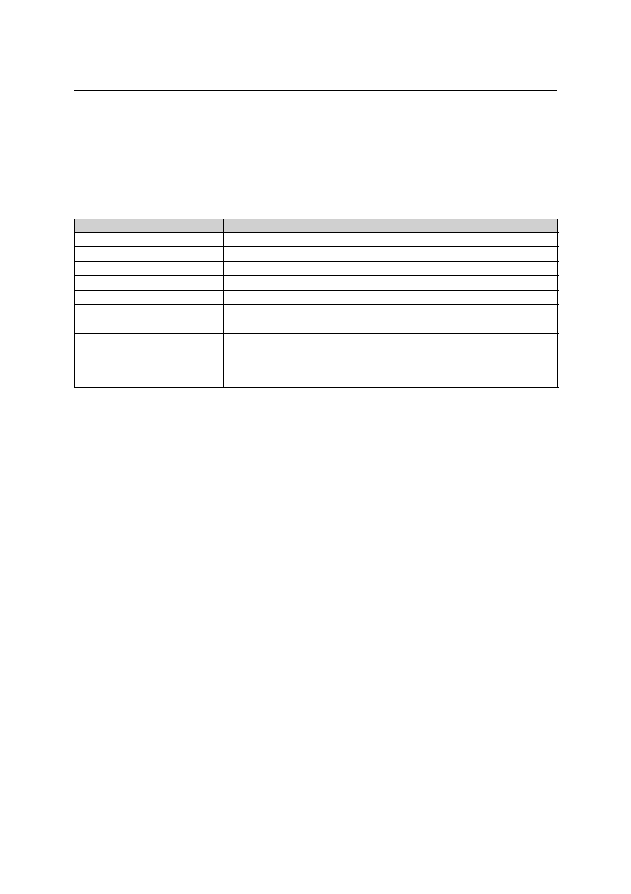
9 Ordering Information
The device is available in the following standard versions.
Non-standard versions require a minimum order of 30,000 units. Contact austriamicrosystems for availability of non-
standard versions.
Standard Part
Threshold (V)
Duration (mS)
Marking
AS1904C23
2.32
100
ASGI
AS1904C26
2.63
100
ASDB
AS1904C31
3.08
100
ASDG
AS1905C23
2.32
100
ASDI
AS1905C26
2.63
100
ASDL
AS1905C31
3.08
100
ASDQ
AS1906C23
2.32
100
ASDS
AS1906C26
2.63
100
ASDV
AS1906C28
2.8
100
ASDX
AS1906C31
3.08
100
ASGK

www.austriamicrosystems.com
Revision 1.4
9 - 9
AS1904, AS1905, AS1906
austria
micro
systems
Data Sheet
Copyrights
Copyright © 1997-2005, austriamicrosystems AG, Schloss Premstaetten, 8141 Unterpremstaetten, Austria-Europe.
Trademarks Registered Æ. All rights reserved. The material herein may not be reproduced, adapted, merged, trans-
lated, stored, or used without the prior written consent of the copyright owner.
All products and companies mentioned are trademarks or registered trademarks of their respective companies.
Disclaimer
Devices sold by austriamicrosystems AG are covered by the warranty and patent indemnification provisions appearing
in its Term of Sale. austriamicrosystems AG makes no warranty, express, statutory, implied, or by description regarding
the information set forth herein or regarding the freedom of the described devices from patent infringement. austriami-
crosystems AG reserves the right to change specifications and prices at any time and without notice. Therefore, prior
to designing this product into a system, it is necessary to check with austriamicrosystems AG for current information.
This product is intended for use in normal commercial applications. Applications requiring extended temperature
range, unusual environmental requirements, or high reliability applications, such as military, medical life-support or life-
sustaining equipment are specifically not recommended without additional processing by austriamicrosystems AG for
each application.
The information furnished here by austriamicrosystems AG is believed to be correct and accurate. However,
austriamicrosystems AG shall not be liable to recipient or any third party for any damages, including but not limited to
personal injury, property damage, loss of profits, loss of use, interruption of business or indirect, special, incidental or
consequential damages, of any kind, in connection with or arising out of the furnishing, performance or use of the tech-
nical data herein. No obligation or liability to recipient or any third party shall arise or flow out of
austriamicrosystems AG rendering of technical or other services.
Contact Information
Headquarters
austriamicrosystems AG
A-8141 Schloss Premstaetten, Austria
Tel: +43 (0) 3136 500 0
Fax: +43 (0) 3136 525 01
e-mail:
info@austriamicrosystems.com
For Sales Offices, Distributors and Representatives, please visit:
http://www.austriamicrosystems.com
austria
micro
systems
≠ a leap ahead