 | –≠–ª–µ–∫—Ç—Ä–æ–Ω–Ω—ã–π –∫–æ–º–ø–æ–Ω–µ–Ω—Ç: AS1918 | –°–∫–∞—á–∞—Ç—å:  PDF PDF  ZIP ZIP |

AS1916 - AS1918
Microprocessor Supervisory Circuits with Manual
Reset and Watchdog
austria
micro
systems
D a ta S h e e t
www.austriamicrosystems.com
Revision 0.52
1 - 13
1 General Description
The AS1916 - AS1918 microprocessor supervisory cir-
cuits were designed to generate a reset when the moni-
tored supply voltage falls below a factory-trimmed
threshold. The reset remains asserted for a minimum
timeout period after the supply voltage stabilizes.
Guaranteed to be in the correct state for V
CC
higher than
+1.0V, these devices are ideal for portable and battery-
powered systems with strict monitoring requirements.
The devices feature factory-trimmed thresholds to moni-
tor a supply voltage between 1.8 and 3.6V.
The devices are available with the reset output types
listed in
Table 1
.
The AS1916 - AS1918 include a manual-reset input for
systems that never fully power down the microproces-
sor.
Additionally, these devices feature a watchdog timer to
help ensure that the processor is operating within proper
code boundaries.
The AS1916 - AS1918 are available in a 5-pin SOT23
package.
Figure 1. Typical Application Diagram
2 Key Features
!
V
CC
Supervisory Range: +1.8 to +3.6V
!
Guaranteed Reset Valid Down to V
CC
= +1.0V
!
Reset Timeout Delay: 215ms
!
Manual Reset Input
!
Three Reset Output Types
- Active-Low Push/Pull (AS1916)
- Active-High Push/Pull (AS1917)
- Active-Low Open-Drain (AS1918)
!
Watchdog Timeout Period: 1.5s
!
Immune to Fast Negative V
CC
Transients
!
External Components Not Required
!
5-pin SOT23 Package
3 Applications
The devices are ideal for portable and battery-powered
systems, embedded controllers, intelligent instruments,
automotive systems, and critical CPU monitoring appli-
cations.
Table 1. Standard Products
Model
Reset Output Type
AS1916
Active-Low Push/Pull
AS1917
Active-High Push/Pull
AS1918
Active-Low Open-Drain
AS1916/
AS1918
External
Reset
CPU
I/O Supply
V
CC
GND
RESETN
I/O
4
WDI
5
V
CC
3
MRN
GND 2
1
RESETN
www.austriamicrosystems.com
Revision 0.52
2 - 13
AS1916 - AS1918
austria
micro
systems
Data Sheet
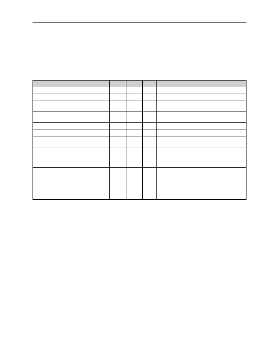
4 Absolute Maximum Ratings
Stresses beyond those listed in
Table 2
may cause permanent damage to the device. These are stress ratings only,
and functional operation of the device at these or any other conditions beyond those indicated in
Electrical Character-
istics on page 3
is not implied. Exposure to absolute maximum rating conditions for extended periods may affect
device reliability.
Table 2. Absolute Maximum Ratings
Parameter
Min
Max
Units
Comments
V
CC
to GND
-0.3
+5.0
V
Open-Drain RESETN
-0.3
+7.0
V
Push/Pull RESET, RESETN
-0.3
V
CC
+
0.3
V
MRN, WDI to GND
-0.3
V
CC
+
0.3
V
Input Current (V
CC
)
20
mA
Output Current (RESET, RESETN)
20
mA
Continuous Power Dissipation
(T
AMB
= +70∫C)
696
mW
Derate 8.7mW/∫C above +70∫C
Operating Temperature Range
-40
+125
∫C
Junction Temperature
+150
∫C
Storage Temperature Range
-65
+150
∫C
Package Body Temperature
+260
∫C
The reflow peak soldering temperature (body
temperature) specified is in accordance with
IPC/JEDEC J-STD-020C "Moisture/Reflow
Sensitivity Classification for Non-Hermetic Solid
State Surface Mount Devices".
The lead finish for Pb-free leaded packages is
matte tin (100% Sn).

www.austriamicrosystems.com
Revision 0.52
3 - 13
AS1916 - AS1918
austria
micro
systems
Data Sheet
5 Electrical Characteristics
V
CC
= +2.7 to +3.6V for AS19xx-T/S/R
,
V
CC
= +2.1 to +2.75V for AS19xx- Z/Y, V
CC
= +1.53 to +2.0V for AS19xx-W/V;
T
AMB
= -40 to +125∫C (unless otherwise specified). Typ values @ T
AMB
= +25∞C.
Table 3. Electrical Characteristics
Symbol
Parameter
1
Conditions
Min
Typ
Max Units
V
CC
Operating Voltage Range
T
AMB
= 0 to +85∫C
1.0
3.6
V
T
AMB
= -40 to +125∫C
1.2
3.6
I
CC
V
CC
Supply Current
(MRN and WDI Not Connected)
V
CC
= +3.6V, No Load,
T
AMB
= -40∫C to +85∫C
5.5
12
µA
V
CC
= +3.6V, No Load,
T
AMB
= -40 to +125∫C
19
V
TH
V
CC
Reset Threshold
(V
CC
Falling)
T
AMB
= -40 to +85∫C
AS19xx-T
2.994
3.08
3.154
V
T
AMB
= -40 to +125∫C
2.972
3.179
T
AMB
= -40 to +85∫C
AS19xx-S
2.848
2.93
3.000
T
AMB
= -40 to +125∫C
2.827
3.024
T
AMB
= -40 to +85∫C
AS19xx-R
2.556
2.63
2.693
T
AMB
= -40 to +125∫C
2.538
2.714
T
AMB
= -40 to +85∫C
AS19xx-Z
2.255
2.32
2.376
T
AMB
= -40 to +125∫C
2.239
2.394
T
AMB
= -40 to +85∫C
AS19xx-Y
2.129
2.19
2.243
T
AMB
= -40 to +125∫C
2.113
2.260
T
AMB
= -40 to +85∫C
AS19xx-W
1.623
1.67
1.710
T
AMB
= -40 to +125∫C
1.612
1.723
T
AMB
= -40 to +85∫C
AS19xx-V
1.536
1.58
1.618
T
AMB
= -40 to +125∫C
1.525
1.631
Reset Threshold
Temperature Coefficient
60
ppm/
∫C
Reset Threshold Hysteresis
8 x
V
TH
mV
t
RD
V
CC
to Reset
Output Delay
V
CC
= V
TH
to (V
TH
- 100mV)
55
µs
t
RP
Reset Timeout Period
T
AMB
= -40 to +85∫C
140
215
280
ms
T
AMB
= -40 to +125∫C
100
320
V
OL
RESETN Output Low
(Push/Pull or Open-Drain)
V
CC
1.0V, I
SINK
= 50µA,
Reset Asserted, T
AMB
= 0 to +85∫C
0.3
V
V
CC
1.2V, I
SINK
= 100µA, Reset
Asserted
0.3
V
CC
2.55V, I
SINK
= 1.2mA,
Reset Asserted
0.3
V
CC
3.3V, I
SINK
= 3.2mA,
Reset Asserted
0.4
V
OH
RESETN Output High
(Push/Pull Only)
V
CC
1.8V, I
SOURCE
= 200µA,
Reset Not Asserted
0.8 x
V
CC
V
V
CC
3.15V, I
SOURCE
= 500µA,
Reset Not Asserted
0.8 x
V
CC
V
CC
3.3V, I
SOURCE
= 800µA,
Reset Not Asserted
0.8 x
V
CC
I
LKG
Open-Drain RESETN Output
Leakage Current
RESETN Not Asserted
1.0
µA
T
AMB
= +25∫C
0.2

www.austriamicrosystems.com
Revision 0.52
4 - 13
AS1916 - AS1918
austria
micro
systems
Data Sheet
V
OH
RESET Output High
(Push/Pull Only)
V
CC
1.0V, I
SOURCE
= 1µA,
Reset Asserted, T
AMB
= 0 to +85∫C
0.8 x
V
CC
V
V
CC
1.50V, I
SOURCE
= 100µA,
Reset Asserted
0.8 x
V
CC
V
CC
2.55V, I
SOURCE
= 500µA,
Reset Asserted
0.8 x
V
CC
V
CC
3.3V, I
SOURCE
= 800µA,
Reset Asserted
0.8 x
V
CC
V
OL
RESET Output Low
(Push/Pull Only)
V
CC
1.8V, I
SINK
= 500µA,
Reset Asserted
0.3
V
V
CC
3.15V, I
SINK
= 1.2mA,
Reset Asserted
0.3
V
CC
3.3V, I
SINK
= 3.2mA,
Reset Asserted
0.4
Manual Reset Input
V
IL
MRN Input voltage
0.3 x
V
CC
V
V
IH
0.7 x
V
CC
MRN Minimum Input Pulse
1
µs
MRN Transient Rejection
90
ns
MRN to Reset Delay
130
ns
MRN Pullup Resistance
25
50
75
k
Watchdog Input
t
WD
Watchdog Timeout Period
T
AMB
= -40 to +85∫C
1.12
1.5
2.4
s
T
AMB
= -40 to +125∫C
0.80
2.60
t
WDI
WDI Pulse Width
2
20 ns
V
IL
WDI Input Voltage
0.3 x
V
CC
V
V
IH
0.7 x
V
CC
I
WDI
WDI Input Current
WDI = V
CC
, Time Average
80
160
µA
WDI = 0, Time Average
-20
-11
1. Over-temperature limits are guaranteed by design and not production tested. Devices tested at +25∫C.
2. Guaranteed by design and not production tested.
Table 3. Electrical Characteristics (Continued)
Symbol
Parameter
1
Conditions
Min
Typ
Max Units
www.austriamicrosystems.com
Revision 0.52
5 - 13
AS1916 - AS1918
austria
micro
systems
Data Sheet
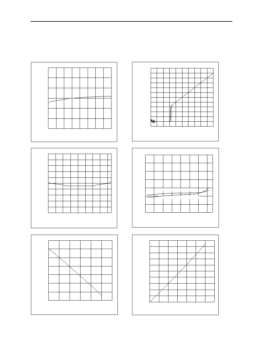
6 Typical Operating Characteristics
T
AMB
= +25∫C (unless otherwise specified).
Figure 2. Normalized Reset Threshold Delay vs.
Figure 3. V
OUT
vs. V
CC
,
V
TH
= 1.58V,
Temperature
Active-Low (Typ)
Figure 4. Reset Timeout Period vs. Temperature
Figure 5. Supply Current vs. Temperature
Figure 6. V
OH
vs. I
SOURCE
; V
CC
= 3.2V
Figure 7. V
OL
vs. I
SINK
; V
CC
= 3.2V
-0.50
0.00
0.50
1.00
1.50
2.00
2.50
3.00
3.50
4.00
4.50
5.00
5.50
0 0.5 1 1.5 2 2.5 3 3.5 4 4.5 5
V
CC
(V)
Output Voltage (V)
e
0.94
0.96
0.98
1
1.02
1.04
1.06
-40 -20
0
20
40
60
80 100 120
Temperature (∞C)
Reset Threshold (V)
e
3
4
5
6
7
8
9
10
-50
-25
0
25
50
75
100 125
Temperature (∞C)
V
CC
Supply Current
(µA)
e
V
CC
= 3.08V T Version
V
CC
= 1.58V V Version
150
160
170
180
190
200
210
220
230
240
250
-40 -20
0
20
40
60 80 100 120
Temperature (∞C)
Reset
T
i
meout
Periode (ms)
2.9
2.95
3
3.05
3.1
3.15
3.2
3.25
0
0.2
0.4
0.6
0.8
1
1.2
I
SOURCE
(mA)
V
OUT
(V)
]
0
0.05
0.1
0.15
0.2
0.25
0.3
0.35
0.4
0.45
0.5
0
1
2
3
4
5
6
7
I
SINK
(mA)
V
OUT
(V)
e

www.austriamicrosystems.com
Revision 0.52
6 - 13
AS1916 - AS1918
austria
micro
systems
Data Sheet
Pin Assignments
7 Pinout
Pin Assignments
Figure 8. Pin Assignments (Top View)
Pin Descriptions
Table 4. Pin Descriptions
Pin
Number
Pin
Name
Description
1
RESETN
Active-Low Reset Output
(AS1916, AS1918). The RESETN signal toggles from high to low
when V
CC
, or MRN is pulled low, or the watchdog triggers a reset. This output signal remains
low for the reset timeout period after all supervised voltages exceed their reset threshold, or
MRN goes low to high, or the watchdog triggers a reset.
RESET
Active-High Reset Output
(AS1917). The RESET signal toggles from low to high when
V
CC
, or MRN is pulled low, or the watchdog triggers a reset. This output signal remains high
for the reset timeout period (see t
RP
on
page 3
) after all supervised voltages exceed their
reset threshold, or MRN goes low to high, or the watchdog triggers a reset.
2
GND
Ground
3
MRN
Active-Low Manual Reset Input
. Pulling this pin low asserts a reset. This pin is connected
to the internal 50k
pullup to V
CC
. This reset remains active as long as MRN is low and for
the reset timeout period (see t
RP
on
page 3
) after MRN goes high.
Note:
If the manual reset feature is not used, this pin should be unconnected or connected
to V
CC
.
4
WDI
Watchdog Input
. If WDI remains high or low for longer than the watchdog timeout period
(see t
WD
on
page 4
), the internal watchdog timer period expires and a reset is triggered for
the reset timeout period (see t
RP
on
page 3
). The internal watchdog timer clears whenever a
reset is a asserted or when WDI senses a rising or falling edge.
Note:
To disable the watchdog feature, this pin must be unconnected or connected to a tri-
state buffer output.
5
V
CC
Supervised Voltage Input
. This pin serves as the supervised supply voltage input.
AS1916 -
AS1918
2
GND
3
MRN
1
RESETN/RESET
4 WDI
5 V
CC
www.austriamicrosystems.com
Revision 0.52
7 - 13
AS1916 - AS1918
austria
micro
systems
Data Sheet
RESET/RESETN
8 Detailed Description
The AS1916 - AS1918 supervisory circuits were designed to generate a reset when the monitored supply voltage falls
below its factory-trimmed trip threshold (see V
TH
on
page 3
), and to maintain the reset for a minimum timeout period
(see t
RP
on
page 3
) after the supply has stabilized.
The integrated watchdog timer
(see Watchdog Input on page 8)
helps mitigate against bad programming code or clock
signals, and/or poor peripheral response.
The active-low manual reset input
(see Manual Reset Input on page 8)
allows for an externally activated system reset.
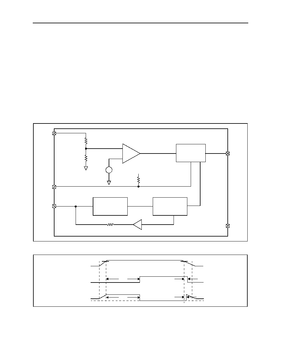
RESET/RESETN
Whenever the monitored supply voltage falls below its reset threshold, the RESET output asserts low or the RESETN
output asserts high. Once the monitored voltage has stabilized, an internal timer keeps the reset asserted for the reset
timeout period (t
RP
). After the t
RP
period, the RESET/RESETN output returns to its original state
(see Figure 10)
.
Figure 9. Functional Diagram of V
CC
Supervisory Application
Figure 10. Reset Timing Diagram
AS1916 - AS1918
Reset Timeout
Delay Generator
Watchdog Transition
Detector
Watchdog
Timer
+
≠
V
CC
1.26V
2
GND
5
V
CC
4
WDI
1
RESETN/
RESET
3
MRN
1V
t
RD
t
RP
t
RP
t
RD
V
TH
V
TH
V
CC
RESETN
RESET
GND
1V

www.austriamicrosystems.com
Revision 0.52
8 - 13
AS1916 - AS1918
austria
micro
systems
Data Sheet
Watchdog Input
Watchdog Input
The integrated watchdog feature can be used to monitor processor activity via pin WDI, and can detect pulses as short
as 50ns. The watchdog requires that the processor toggle the watchdog logic input at regular intervals, within a speci-
fied minimum timeout period (1.5s, typ). A reset is asserted for the reset timeout period. As long as reset is asserted,
the timer remains cleared and is not incremented. When reset is deasserted, the watchdog timer starts counting
(
Figure 11
).
Note:
The watchdog timer can be cleared with a reset pulse or by toggling WDI.
Figure 11. Watchdog Timing Relationship
The watchdog is internally driven low during most (87.5%) of the watchdog timeout period (see t
WD
on
page 4
) and
high for the rest of the watchdog timeout period. When pin WDI is left unconnected, this internal driver clears the
watchdog timer every 1.4s. When WDI is tri-stated or is not connected, the maximum allowable leakage current is
10µA and the maximum allowable load capacitance is 200pF.
Note:
The watchdog function can be disabled by leaving pin WDI unconnected or connecting it to a tri-state output
buffer.
Manual Reset Input
The active-low pin MRN is used to force a manual reset. This input can be driven by CMOS logic levels or with open-
drain collector outputs.
Pulling MRN low asserts a reset which will remain asserted as long as MRN is kept low, and for the timeout period (see
t
RP
on
page 3
) after MRN goes high (140ms min). The manual reset circuitry has an internal 50k
pullup resistor, thus
it can be left open if not used.
To create a manual-reset circuit, connect a normally open momentary switch from pin MRN to GND
(see Figure 1 on
page 1)
; external debounce circuitry is not required in this configuration.
If MRN is driven via long cables or the device is used in a noisy environment, a 0.1µF capacitor between pin MRN and
GND will provide additional noise immunity.
t
RST
The RESET signal is the inverse of the RESETN signal.
t
WD
V
CC
RESETN
WDI
t
RP
t
RP

www.austriamicrosystems.com
Revision 0.52
9 - 13
AS1916 - AS1918
austria
micro
systems
Data Sheet
Watchdog Input Current
9 Application Information
Watchdog Input Current
The watchdog input is driven through an internal buffer and an internal series resistor from the watchdog timer
(see
Figure 11 on page 8)
. When pin WDI is left unconnected (watchdog disabled), the watchdog timer is serviced within the
watchdog timeout period (see t
WD
on
page 4
) by a low-high-low pulse from the counter chain.
For minimum watchdog input current (minimum overall power consumption), pull WDI low for most of the watchdog
timeout period, pulsing it low-high-low once within the first 7/8 (87.5%) of the watchdog timeout period to reset the
watchdog timer.
Note:
If WDI is externally driven high for the majority of the timeout period, up to 160µA can flow into pin WDI.
Interfacing to Bi-Directional CPU Reset Pins
Since the reset output of the AS1918 is open drain, this device interfaces easily with processors that have bi-direc-
tional reset pins. Connecting the processor reset output directly to the AS1918 RESETN pin with a single pullup resis-
tor
(see Figure 12)
allows the AS1918 to assert a reset.
Figure 12. AS1918 RESETN-to-CPU Bi-Directional Reset Pin
Fast Negative-Going Transients
Fast, negative-going V
CC
transients normally do not require the CPU to be shutdown. The AS1916 - AS1918 are virtu-
ally immune to such transients. Resets are issued to the CPU during power-up, powerdown, and brownout conditions.
Note:
V
CC
transients that go 100mV below the reset threshold and last
55µs typically will not assert a reset pulse.
Valid Reset to V
CC
= 0
The AS1916 - AS1918 are guaranteed to operate properly down to V
CC
= 1V.
For AS1916 and AS1917 applications requiring valid reset levels down to V
CC
= 0, a pulldown resistor to active-low
outputs and a pullup resistor to active-high outputs will ensure that the reset line is valid during the interval where the
reset output can no longer sink or source current.
Watchdog Tips
Careful consideration should be taken when implementing the AS1916 - AS1918 watchdog feature.
One method of supervising software code execution is to set/reset the watchdog input at different places in the code,
rather than pulsing the watchdog input high-low-high or low-high-low. This method avoids a loop condition in which the
watchdog timer would continue to be reset inside the loop, preventing the watchdog from ever timing out.
AS1918
CPU
Reset
Generator
V
CC
RESETN
GND
V
CC
V
CC
1
RESETN
GND 2
V
CC
5
www.austriamicrosystems.com
Revision 0.52
10 - 13
AS1916 - AS1918
austria
micro
systems
Data Sheet
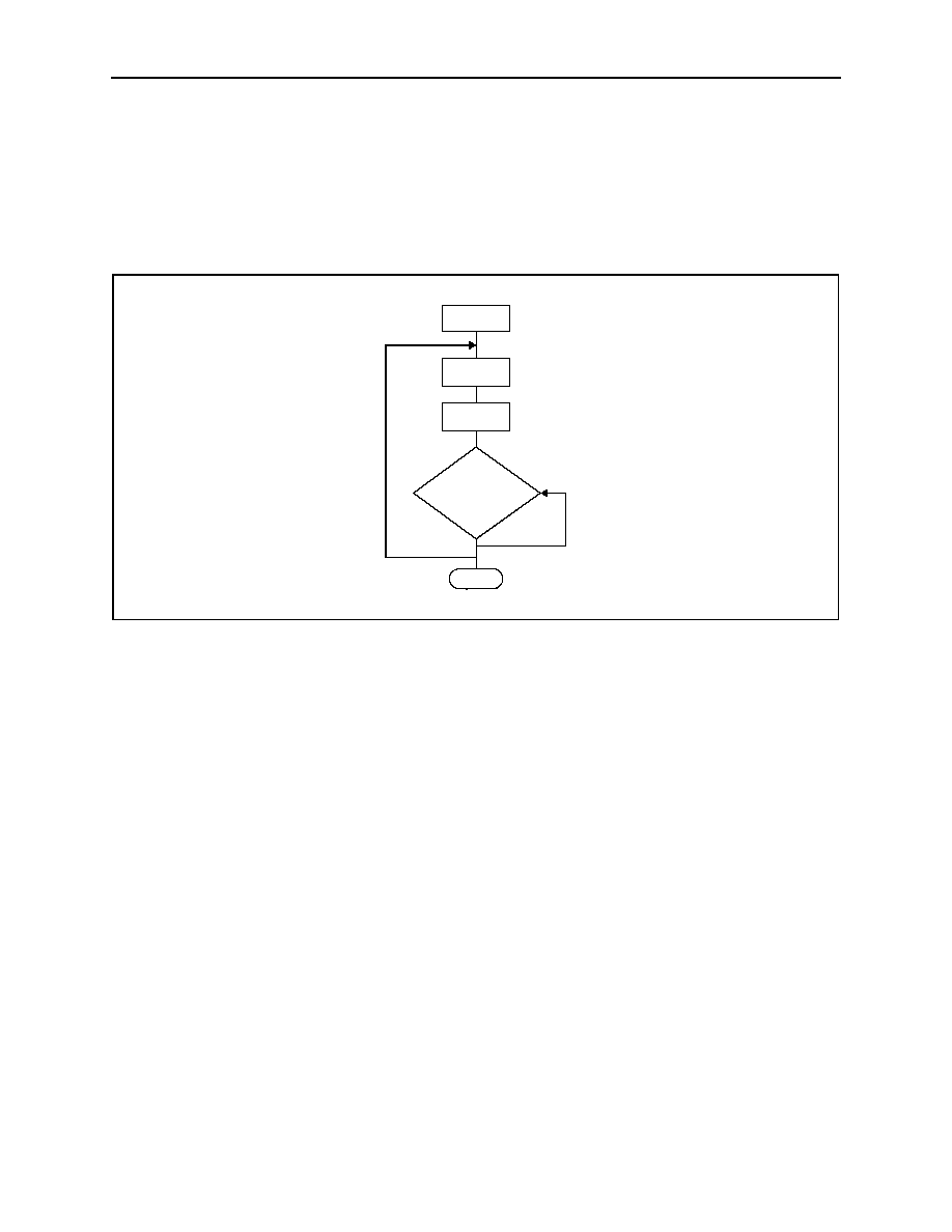
Watchdog Tips
Figure 13
shows a flowchart where the input/output driving the watchdog is set high at the beginning of the routine, set
low at the beginning of every subroutine, then set high again when the routine returns to the beginning. If the routine
should hang in a subroutine, the problem would quickly be corrected, since the I/O is continually set low and the watch-
dog timer is allowed to time out, causing a reset or interrupt to be issued
(see Watchdog Input Current on page 9)
. This
method results in higher averaged WDI input current over time than a case where WDI is held low for the majority
(87.5%) of the timeout period and periodically pulsing it low-high-low.
Figure 13. Example Watchdog Programming Flowchart
Start
Set WDI
High
Subroutine or
Program Loop
Set WDI Low
Return
Program
Code
www.austriamicrosystems.com
Revision 0.52
11 - 13
AS1916 - AS1918
austria
micro
systems
Data Sheet
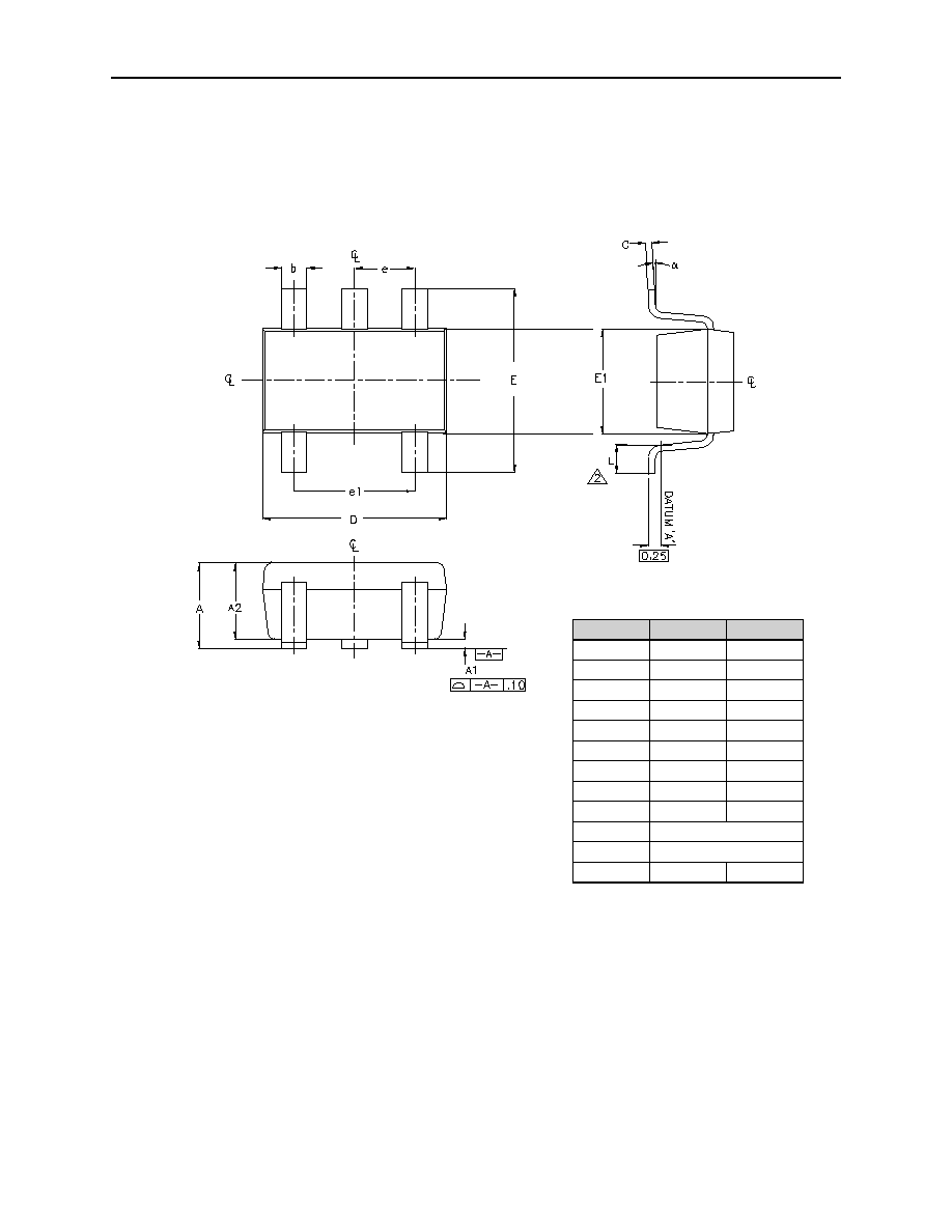
10 Package Drawings and Markings
The devices are available in an 5-pin SOT23 package.
Figure 14. 5-pin SOT23 Package
Symbol
Min
Max
A
0.90
1.45
A1
0.00
0.15
A2
0.90
1.30
b
0.30
0.50
C
0.09
0.20
D
2.80
3.05
E
2.60
3.00
E1
1.50
1.75
L
0.30
0.55
e
0.95 REF
e1
1.90 REF
0∫
8∫
Notes:
1. All dimensions in millimeters.
2. Foot length measured at intercept point between datum A and lead
surface.
3. Package outline exclusive of mold flash and metal burr.
4. Package outline inclusive of solder plating.
5. Complies with EIAJ SC74.
6. PKG ST 0003 Rev A supersedes SOT23-D-2005 Rev C.

www.austriamicrosystems.com
Revision 0.52
12 - 13
AS1916 - AS1918
austria
micro
systems
Data Sheet
11 Ordering Information
The devices are available as the standard products shown in
Table 5
.
Table 5. Ordering Information
Model
Marking
Description
Threshold Delivery Form
Package
AS1916S-T
ASIO
Active-Low Push/Pull Supervisory Circuit
with Watchdog and Manual Reset
2.93V
Tape and Reel
5-pin SOT23
AS1916R-T
ASIP
Active-Low Push/Pull Supervisory Circuit
with Watchdog and Manual Reset
2.63V
Tape and Reel
5-pin SOT23
AS1916Z-T
ASIQ
Active-Low Push/Pull Supervisory Circuit
with Watchdog and Manual Reset
2.32V Tape
and
Reel
5-pin SOT23
AS1916V-T
ASIR
Active-Low Push/Pull Supervisory Circuit
with Watchdog and Manual Reset
1.58V
Tape and Reel
5-pin SOT23
AS1917S-T
ASIS
Active High Push/Pull Supervisory Circuit
with Watchdog and Manual Reset
2.93V
Tape and Reel
5-pin SOT23
AS1917R-T
ASIT
Active High Push/Pull Supervisory Circuit
with Watchdog and Manual Reset
2.63V
Tape and Reel
5-pin SOT23
AS1917Z-T
ASIU
Active High Push/Pull Supervisory Circuit
with Watchdog and Manual Reset
2.32V
Tape and Reel
5-pin SOT23
AS1917V-T
ASIV
Active High Push/Pull Supervisory Circuit
with Watchdog and Manual Reset
1.58V Tape
and
Reel
5-pin SOT23
AS1918S-T
ASIW
Active-Low Open Drain Supervisory Circuit
with Watchdog and Manual Reset
2.93V
Tape and Reel
5-pin SOT23
AS1918R-T
ASIX
Active-Low Open Drain Supervisory Circuit
with Watchdog and Manual Reset
2.63V
Tape and Reel
5-pin SOT23
AS1918Z-T
ASIY
Active-Low Open Drain Supervisory Circuit
with Watchdog and Manual Reset
2.32V
Tape and Reel
5-pin SOT23
AS1918V-T
ASIZ
Active-Low Open Drain Supervisory Circuit
with Watchdog and Manual Reset
1.58V
Tape and Reel
5-pin SOT23

www.austriamicrosystems.com
Revision 0.52
13 - 13
AS1916 - AS1918
austria
micro
systems
Data Sheet
Copyrights
Copyright © 1997-2005, austriamicrosystems AG, Schloss Premstaetten, 8141 Unterpremstaetten, Austria-Europe.
Trademarks Registered Æ. All rights reserved. The material herein may not be reproduced, adapted, merged, trans-
lated, stored, or used without the prior written consent of the copyright owner.
All products and companies mentioned are trademarks or registered trademarks of their respective companies.
Disclaimer
Devices sold by austriamicrosystems AG are covered by the warranty and patent indemnification provisions appearing
in its Term of Sale. austriamicrosystems AG makes no warranty, express, statutory, implied, or by description regarding
the information set forth herein or regarding the freedom of the described devices from patent infringement. austriami-
crosystems AG reserves the right to change specifications and prices at any time and without notice. Therefore, prior
to designing this product into a system, it is necessary to check with austriamicrosystems AG for current information.
This product is intended for use in normal commercial applications. Applications requiring extended temperature
range, unusual environmental requirements, or high reliability applications, such as military, medical life-support or life-
sustaining equipment are specifically not recommended without additional processing by austriamicrosystems AG for
each application. For shipments of less than 100 parts the manufacturing flow might show deviations from the standard
production flow, such as test flow or test location.
The information furnished here by austriamicrosystems AG is believed to be correct and accurate. However,
austriamicrosystems AG shall not be liable to recipient or any third party for any damages, including but not limited to
personal injury, property damage, loss of profits, loss of use, interruption of business or indirect, special, incidental or
consequential damages, of any kind, in connection with or arising out of the furnishing, performance or use of the tech-
nical data herein. No obligation or liability to recipient or any third party shall arise or flow out of
austriamicrosystems AG rendering of technical or other services.
Contact Information
Headquarters
austriamicrosystems AG
A-8141 Schloss Premstaetten, Austria
Tel: +43 (0) 3136 500 0
Fax: +43 (0) 3136 525 01
e-mail:
info@austriamicrosystems.com
For Sales Offices, Distributors and Representatives, please visit:
http://www.austriamicrosystems.com
austria
micro
systems
≠ a leap ahead