
AP1301/2/4/5
Single Coil Fan Motor Full Wave Driver
This datasheet contains new product information. Anachip Corp. reserves the rights to modify the product specification without notice. No liability is assumed as a result of the use of
this product. No rights under any patent accompany the sale of the product.
Rev. 0.2 Apr. 16, 2004
1/5
Features
- Compatible to a Hall element
- Operating voltage (V
CC
) : 4V to 20V
- Lock shutdown and automatic restart
- Speed indication output (FG) named as AP1301/4
- Rotation detection output (RD) named as
AP1302/5
- Output current(AP1301/2) I
O
=500mA
(max)
- Output current(AP1304/5) I
O
=350mA
(max)
- Operating temperature (T
opr
) : -30�C to +85�C
- SOP-8L/ SOP-8L EP package
- Include Thermal Shutdown circuit
Application
- CPU cooling fans
General Description
The AP1304/5 is single phase full wave drive
design, which is suited for small fans (such as CPU
cooling fans). The low switching noise and effective
motor drive are another advantage. All functions,
including lock shutdown, automatic restart, rotation
detection (RD), and speed indication output (FG)
have been incorporated into one chip. When the
motor is under lock condition, lock shutdown
function turns off the output current. When the lock
condition is removed, the IC automatically restarts
and allows DC fan to run. In addition, the RD
function is to detect the motor status and the FG is
to provide the rotation speed.
The AP1301/2 are heat sink version of AP1304/5.
From function wise, AP1301 is the same as
AP1304, and AP1302 is the same as AP1305.
Pin Assignment
AP1301/2/4/5
3
4
8
7
6
5
2
1
IN+
IN-
OUT1
CT
GND
OUT2
VCC
RD/FG
( Top view )
SOP-8L
Pin Descriptions
Name
Description
VCC Power
input
IN+ Hall
input
RD/FG Rotation detection / Speed indication
IN- Hall
input
GND Ground
CT Timing
capacitor
OUT2
Driver output
OUT1
Driver output
Ordering Information
Function
Package
S: SOP-8L
SP: SOP-8L EP
AP130X X - X X X
Packing
Blank : Tube
A : Taping
- RD output (1305)
- FG output (1304)
without heat sink
- RD output (1302)
- FG output (1301)
with heat sink
Blank: Normal
L: Lead Free
Lead
Wafer Body
Blank or
A~Z : if necessary
to specify
AP1301/2/4/5
Single Coil Fan Motor Full Wave Driver
Anachip Corp.
www.anachip.com.tw
Rev 0.2 Apr.16, 2004
2/5
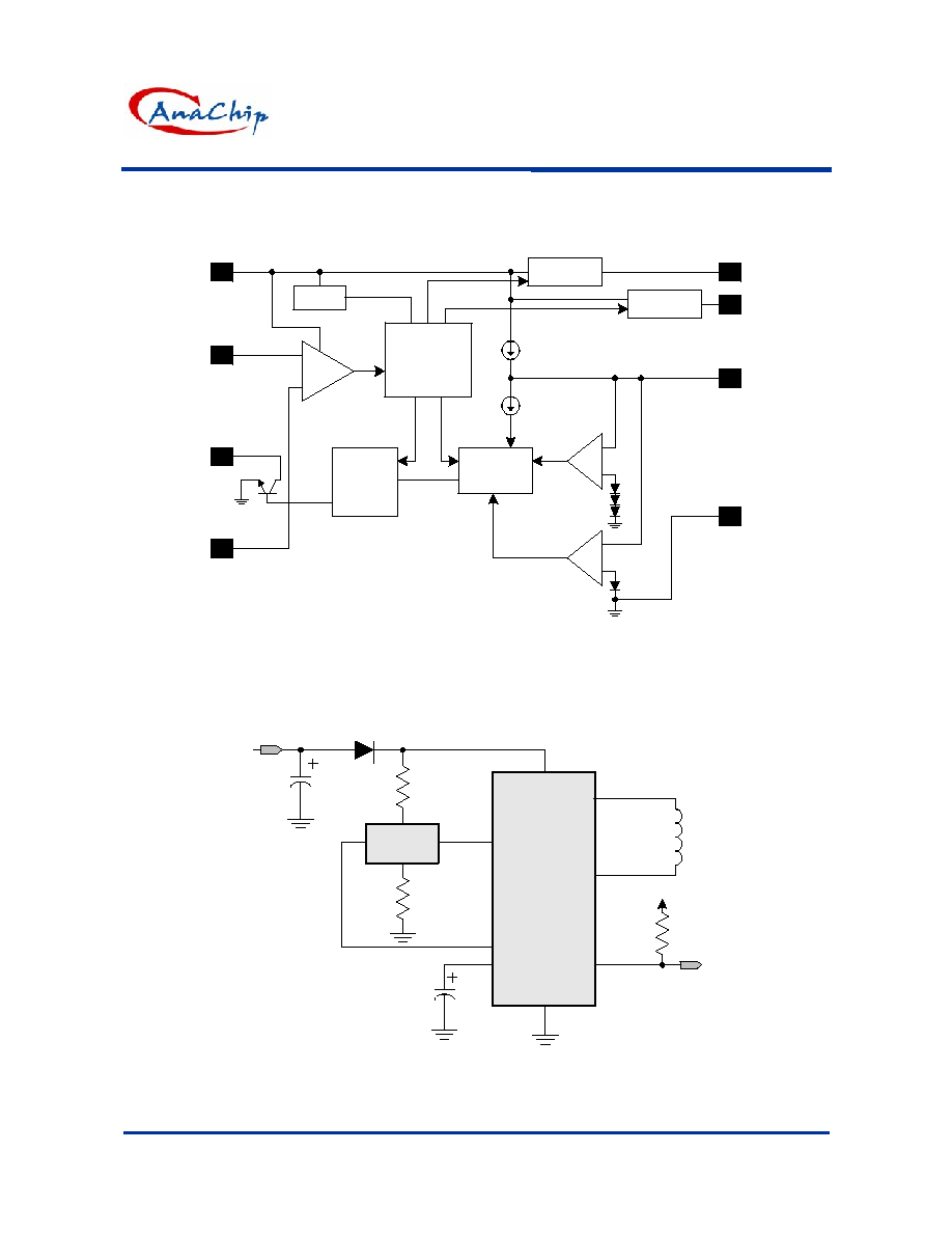
Block Diagram
7
2
8
1
5
3
6
4
Reg.
Hall
amp
Driver1
Driver 2
Control Logic
Lock
Detection
Automatic
Restart
VCC
IN+
RD/
FG
IN-
GND
CT
OUT2
OUT1
+
-
Application Circuit
VCC
IN+
IN-
Hall
element
CT
GND
D1
R1
C1
input
RD(FG)
OUT1
OUT2
AP1301/2/4/5
R2
C2
R6
RD(FG)
output
V1
L1
AP1301/2/4/5
Single Coil Fan Motor Full Wave Driver
Anachip Corp.
www.anachip.com.tw
Rev 0.2 Apr.16, 2004
3/5
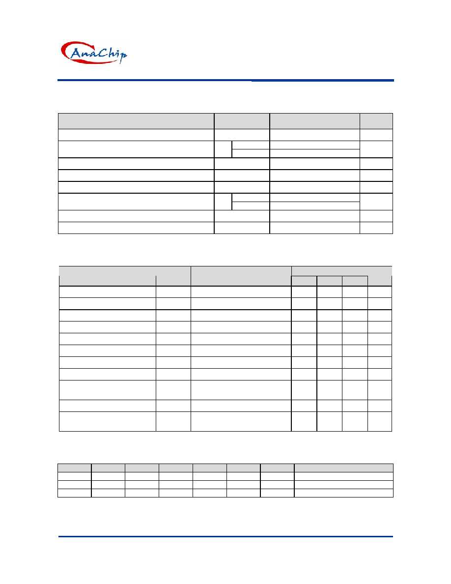
Absolute Maximum Ratings
(T
A
=25�C)
Parameter
Symbol
Rating
Unit
Input voltage
V
CC
20
V
AP1304/5
350
Output current
I
OUT
AP1301/2
500
mA
Maximum output withstand voltage
Vout
20
V
RD/FG maximum output withstand voltage
Vr/Vf
20
V
RD/FG maximum output current
Ir/If
5
mA
AP1304/5
550*(note1)
Allowable power dissipation
P
D
AP1301/2
1000
mW
Operating temperature
T
OPR
-30
to
+85
�C
Storage temperature
T
STG
-55
to
+150
�C
*note1 : Reduced by 5.5mW for each increase in Ta of 1�C over 25 �C
Electrical Characteristics
( T
A
=25�C, V
CC
=5V, unless otherwise noted)
Rating
Parameter
Symbol
Conditions
Min.
Typ.
Max.
Unit
Power supply voltage
Vcc
4
--
20
V
Hall input voltage (DC+AC)
V
BH
Includes the amplitude of signal
0.2
--
V
CC
-1.5
V
Supply current
I
CC
The output is off
--
6.5
10
mA
Charge current
I
CHG
V
CT
=
1.5V
1.9 2.8 3.7 uA
Discharge current
I
DHG
V
CT
= 1.5V
0.32
0.46
0.60
uA
Charge/discharge ratio
R
CD
I
GHG
/I
DCHG
5.0
6.0
7.0
--
Output Low Level Voltage
Vol
Io=200mA
0.2
0.3
V
Output High Level Voltage
Voh
Io=200mA
3.9
4.1
V
Hall input sensitivity
V
HN
Zero peak value (including
offset and hysteresis)
7 15
mV
RD/FG pin output low
V
RDL,
Vfgl I
RD ,
Ifg = 5mA
--
0.1
0.3
V
RD/FG output pin leakage
current
Irdl,Ifgl Vrd,Vfg=15V
30
uA
Truth Table
IN-
IN+
CT
OUT1
OUT2
RD
FG
Mode
H L L H L L L
Rotating
L H L L H L H
Rotating
- - H
off
off
off -
Lockup
protection
activated
Latch-type RD output is low during rotation and high during stop
AP1301/2/4/5
Single Coil Fan Motor Full Wave Driver
Anachip Corp.
www.anachip.com.tw
Rev 0.2 Apr.16, 2004
4/5
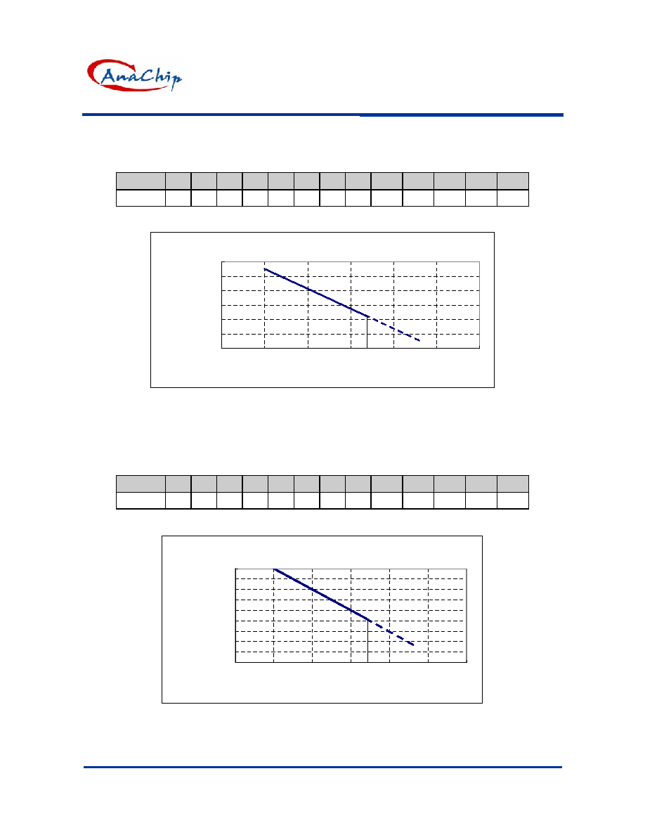
Performance Characteristics (without heat sink AP1304/5)
Ta (
�C)
25
50
60
70
80
85
90
95
100
105
110
115
120
Pd
(mW) 550 413 358 303 248 220 193 165
138
110
83
55
28
Power Dissipation Curve
0
100
200
300
400
500
600
0
25
50
75
100
125
150
Ta ( C)
Pd (m W )
85
NoteSOP-8L package.
Performance Characteristics (with heat sink AP1301/2)
Ta (
�C)
25
50
60
70
80
85
90
95
100
105
110
115
120
Pd (mW) 1000 800 720 640 560 520 480 440
400
360
320
280
240
Power Dissipation Curve
100
200
300
400
500
600
700
800
900
1000
0
25
50
75
100
125
150
Ta ( C)
Pd (m W )
85
NoteSOP-8L EP package.
AP1301/2/4/5
Single Coil Fan Motor Full Wave Driver
Anachip Corp.
www.anachip.com.tw
Rev 0.2 Apr.16, 2004
5/5
Marking Information
Blank : normal
L : Lead Free Package
Y: Year, "01"=2001
"02"=2002
WW: Xth week,01-52
3
4
2
1
8
7
6
5
SOP-8L
Part Number
Logo
Date code
X: internal code
AC
AP1301/2/4/5
YY WW X X
(Top View)
~
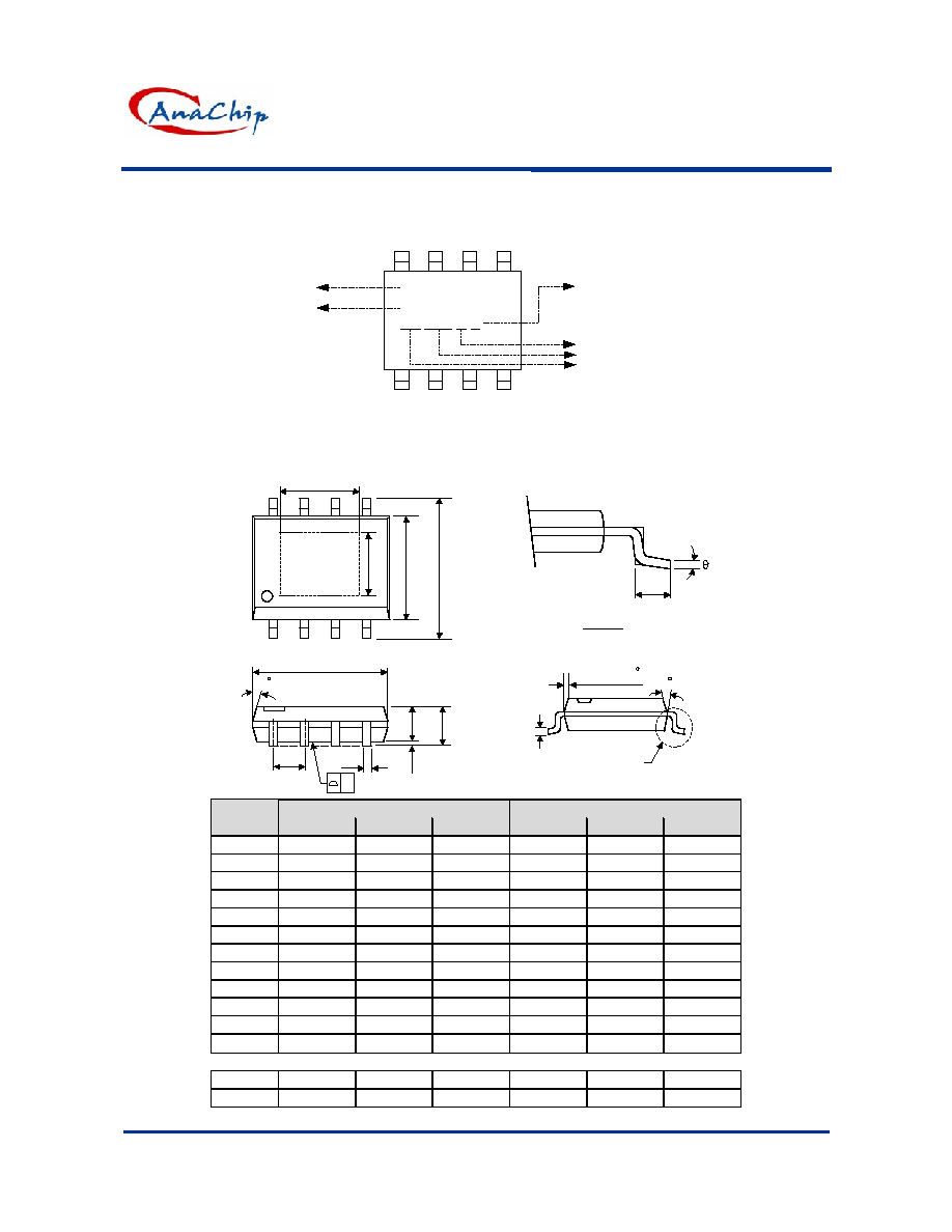
Package Information
Package Type: SOP-8L ( Normal / Expose Pad )
VIEW "A"
L
C
VIEW "A"
H
E
A
A2
A1
B
e
D
7 (4X)
0.015x45
7 (4X)
y
Y
X
Expose Pad
Dimensions In Millimeters
Dimensions In Inches
Symbol
Min.
Nom.
Max.
Min.
Nom.
Max.
A 1.40 1.60 1.75
0.055
0.063
0.069
A1 0.10 - 0.25 0.040 - 0.100
A2 1.30 1.45 1.50 0.051
0.057
0.059
B 0.33 0.41 0.51
0.013
0.016
0.020
C 0.19 0.20 0.25
0.0075
0.008
0.010
D 4.80 5.05 5.30 0.189
0.199
0.209
E 3.70 3.90 4.10
0.146
0.154
0.161
e - 1.27 - -
0.050
-
H 5.79 5.99 6.20 0.228
0.236
0.244
L 0.38 0.71 1.27
0.015
0.028
0.050
y - - 0.10 - -
0.004
0
O
- 8
O
0
O
- 8
O
(Expose pad)
X - 2.92 - -
0.115
-
Y - 2.34 - -
0.092
-