AP1307
Two Coil Fan Motor Predriver
This datasheet contains new product information. Anachip Corp. reserves the rights to modify the product specification without notice. No liability is assumed as a result of the use of
this product. No rights under any patent accompany the sale of the product.
Rev. 0.4 Apr 16, 2004
1/5
Features
- Compatible to a Hall element
- Operating voltage (V
CC
) : 4V to 28V
- Lock shutdown and automatic restart
- Rotation detection (RD) output
- Output current I
O
=70mA
(max)
- Operating temperature (T
opr
) : -30∫C to +85∫C
- SOP8 package
- Include Thermal Shutdown circuit
Application
- High voltage, high current brushless DC fan
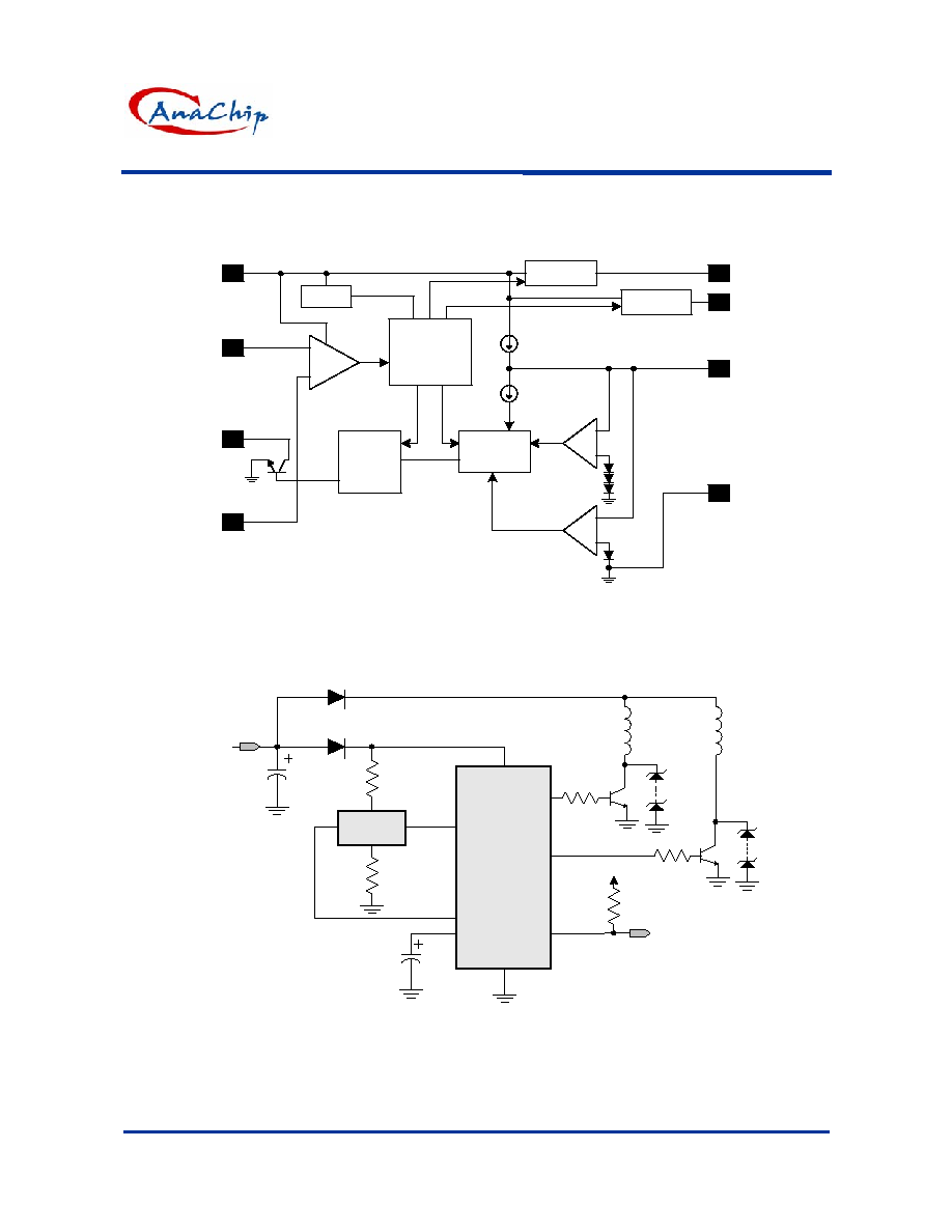
General Description
The AP1307 fan motor predriver is suited for
two-coil brush-less DC fan. All functions, including
lock shutdown, automatic restart, rotation detection
(RD), have been incorporated into one chip. When
the motor is under lock condition, lock shutdown
function turns off the output current. When the lock
condition is removed, the IC automatically restarts
and allows DC fan to run. In addition, the RD
function is to detect the motor status.
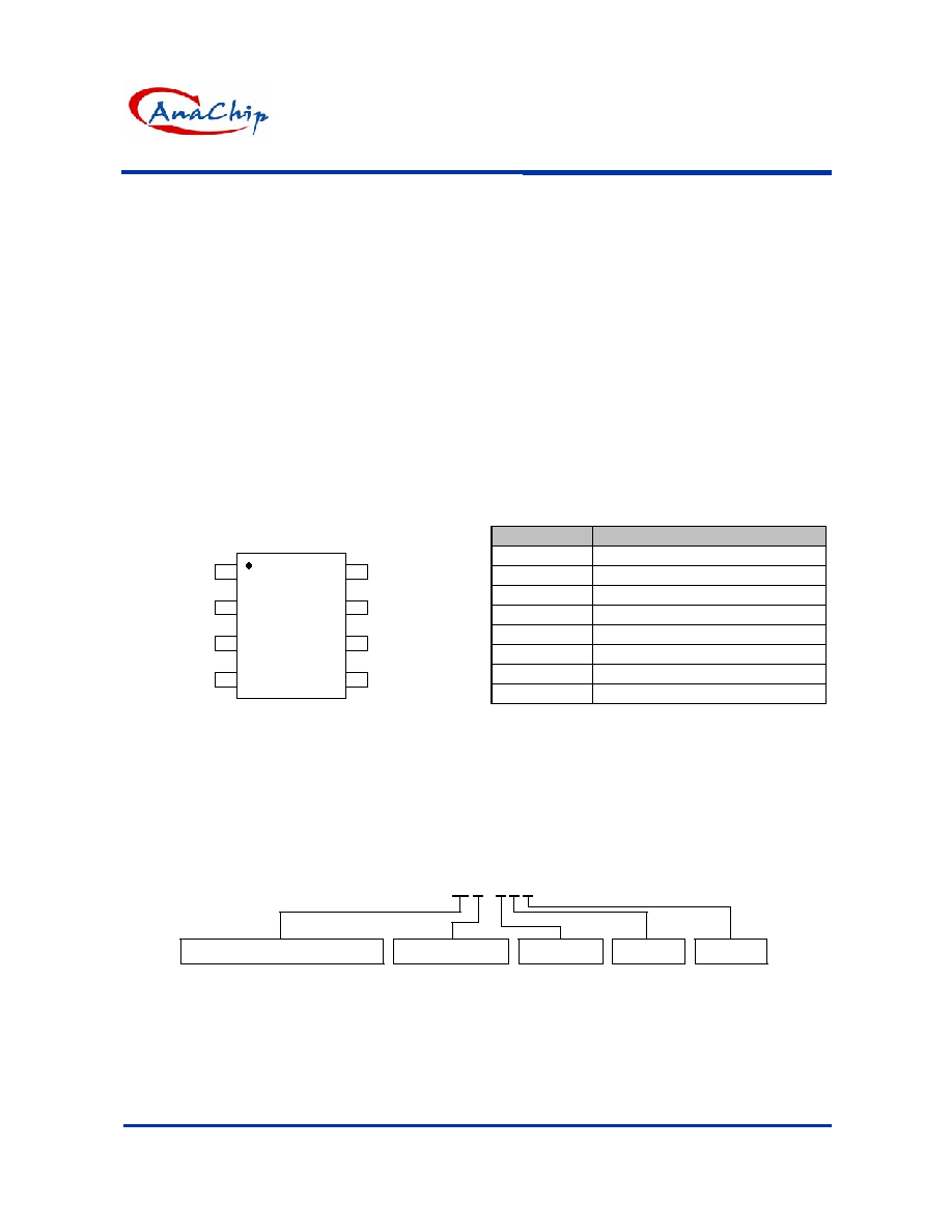
Pin Assignment
AP1307
3
4
8
7
6
5
2
1
HS(+)
VCC
HS(-)
RD
GND
CT
OUT2
OUT1
( Top view )
SOP-8L
Pin Descriptions
Name
Description
VCC Power
input
HS(+) Hall
input
RD Rotation
detection
HS(-) Hall
input
GND Ground
CT Timing
capacitor
OUT2 Driver
output
OUT1 Driver
output
Ordering Information
Function
Package
S: SOP-8L
AP1307 X - X X X
Packing
Blank : Tube
A : Taping
Blank: Normal
L: Lead Free
Lead
Wafer Body
Blank or
A~Z : if necessary
to specify
- Lock shutdown and automatic restart
- RD output
- Thermal shutdown

AP1307
Two Coil Fan Motor Predriver
Anachip Corp.
www.anachip.com.tw
Rev 0.4 Apr 16, 2004
3/5
Absolute Maximum Ratings
(T
A
=25∫C)
Parameter
Symbol
Rating
Unit
Input voltage
V
CC
30
V
Output current
I
OUT
70
mA
Allowable power dissipation
P
D
550*(note1)
mW
Operating temperature
T
OPR
-30 to +85
∫C
Storage temperature
T
STG
-55 to +125
∫C
RD V
CEO
D.C. Voltage
V
CEO
36
V
*note1 : Reduced by 5.5mW for each increase in Ta of 1
∫C
over 25
∫C
Electrical Characteristics
( T
A
=25∫C, V
CC
=12V, unless otherwise noted)
Rating
Parameter
Symbol
Conditions
Min.
Typ.
Max.
Unit
Input voltage
V
IN
4 -- 28 V
Hall input voltage
V
BH
Includes the amplitude of signal
1
--
V
CC
-0.5
V
Supply current
I
CC
The output is off
--
2.8
5
mA
Hall amp input hysteresis (+)
V
HYS
3
--
15 mV
Charge current
I
CHG
V
CT
= 1.5V
2
3.45
5.25
uA
Discharge current
I
DHG
V
CT
= 1.5V
0.35
0.8
1.45
uA
Charge/discharge ratio
R
CD
I
CHG
/I
DCHG
3
4.5
8
--
Clamp voltage
V
CL
2.2 2.6 3.0 V
Comparator voltage
V
CP
0.4 0.6 0.8 V
Output high level
V
OH
I
O
= 10mA
10
10.5
--
V
RD pin output low
V
RDL
I
RD
= 5mA
--
--
0.5
V
RD pin sink current capacity
I
RD
V
RDL
= 2V
8
--
--
mA

AP1307
Two Coil Fan Motor Predriver
Anachip Corp.
www.anachip.com.tw
Rev 0.4 Apr 16, 2004
4/5
Performance Characteristics
Ta (
∞C)
25
50
60
70
80
85
90
95
100
105
110
115
120
Pd
(mW) 550 413 358 303 248 220 193 165
138
110
83
55
28
Power Dissipation Curve
0
100
200
300
400
500
600
0
25
50
75
100
125
150
Ta ( C)
Pd (m W )
85
NoteSOP-8L package.
Marking Information
Blank : normal
L : Lead Free Package
Y: Year, "01"=2001
"02"=2002
WW: Xth week,01-52
3
4
2
1
8
7
6
5
SOP-8L
Part Number
Logo
Date code
X: ID code
AC
AP1307
YY WW X X
(Top View)
~
AP1307
Two Coil Fan Motor Predriver
Anachip Corp.
www.anachip.com.tw
Rev 0.4 Apr 16, 2004
5/5
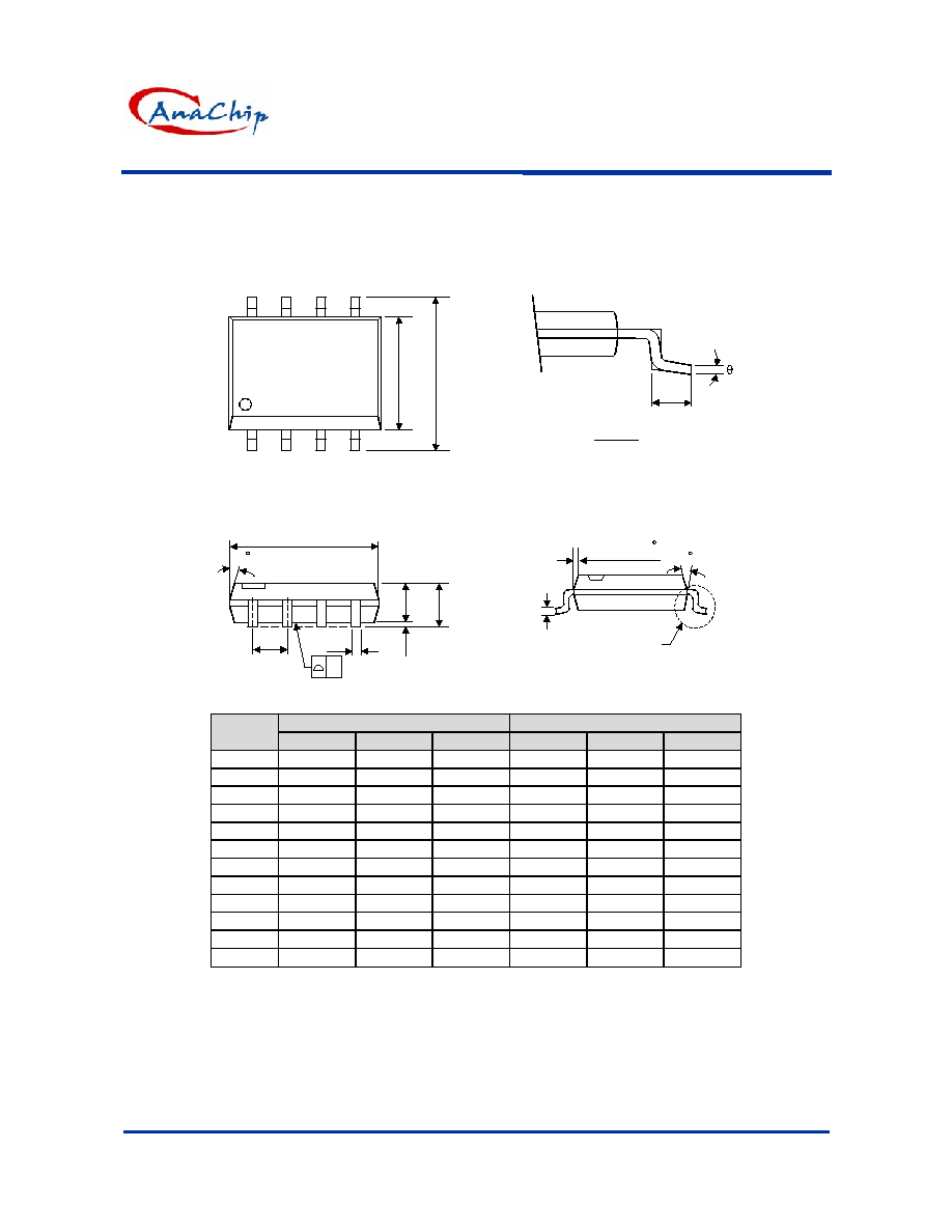
Package Information
Package Type: SOP-8L
VIEW "A"
L
C
VIEW "A"
H
E
A
A2
A1
B
e
D
7 (4X)
0.015x45
7 (4X)
y
Dimensions In Millimeters
Dimensions In Inches
Symbol
Min.
Nom.
Max.
Min.
Nom.
Max.
A 1.40 1.60 1.75
0.055
0.063
0.069
A1 0.10 - 0.25 0.040 - 0.100
A2 1.30 1.45 1.50 0.051
0.057
0.059
B 0.33 0.41 0.51
0.013
0.016
0.020
C 0.19 0.20 0.25
0.0075
0.008
0.010
D 4.80 5.05 5.30 0.189
0.199
0.209
E 3.70 3.90 4.10
0.146
0.154
0.161
e - 1.27 - -
0.050
-
H 5.79 5.99 6.20 0.228
0.236
0.244
L 0.38 0.71 1.27
0.015
0.028
0.050
y - - 0.10 - -
0.004
0
O
- 8
O
0
O
- 8
O