
AP1521
White LED Step-Up Converter
This datasheet contains new product information. Anachip Corp. reserves the rights to modify the product specification without notice. No liability is assumed as a result of the use of
this product. No rights under any patent accompany the sale of the product.
Rev. 0.1 Apr. 27, 2004
1/8
Features
- Inherently Matched LED Current
- Drives Up to Four LEDs from a 3.2V Supply
- Drives Up to Six LEDs from a 5V Supply
- High Efficiency: 84% Typical
- Fast 1MHz Switching Frequency
- 36V Rugged Bipolar Switch
- Low Profile SOT23-5 Pb-Free Packaging
Applications
- Cellular Phones
- PDAs, Hand-held Computers
- Digital Cameras
- MP3 Players
- GPS Receivers
General Description
The AP1521 is a step-up DC/DC converter
specifically designed to drive white LEDs with a
constant current. The device can drive two, three or
four LEDs in series from a Li-Ion cell. Series
connection of the LEDs provides identical LED
currents resulting in uniform brightness and
eliminates the need for ballast resistors. The
AP1521 switches at 1MHz that allows the use of
tiny external components. A low 300mV feedback
voltage minimizes power loss in the current setting
resistor for better efficiency.
Pin Assignments
V
IN
SHDN
SW V
SS
FB
Top View
SOT23-5L
Pin Descriptions
Name
Description
SW
Switch Pin. Connect inductor/diode
here. Minimize trace area at this pin
to reduce EMI.
V
SS
GND
pin
FB
Feedback Pin. Reference voltage is
310mV. Connect cathode of lowest
LED and resistor here. Calculate
resistor value according to the
formula R
FB
= 310mV / I
LED
SHDN
Shutdown Pin. Tie to 1.5V or higher
to enable the device0.4V or less to
disable the device.
V
IN
Input Supply Pin. Must be locally
bypassed.
Ordering Information
Package
W: SOT23-5L
AP1521 X X
Packing
Blank : Tube
A : Taping
AP1521
White LED Step-Up Converter
Anachip Corp.
www.anachip.com.tw Rev. 0.1 Apr. 27, 2004
2/8
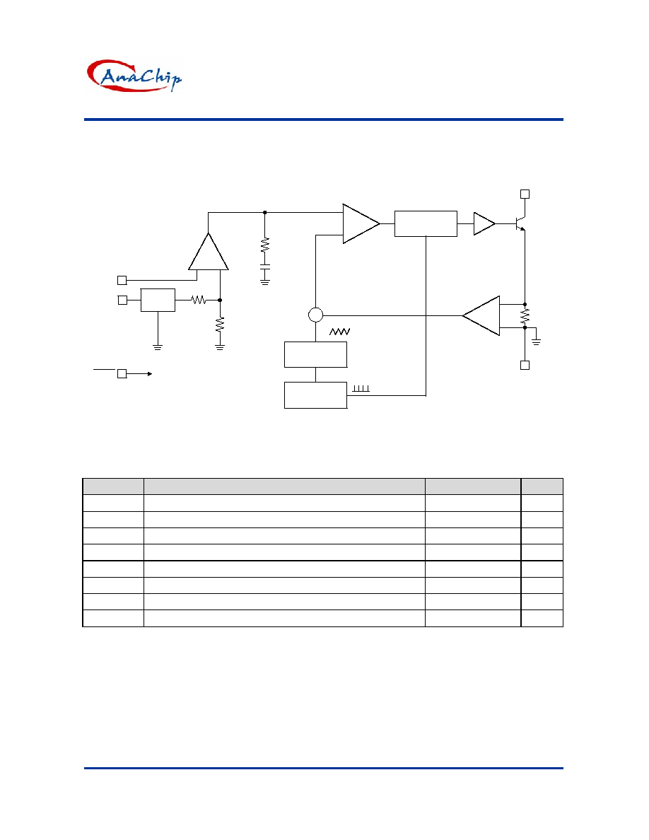
Block Diagram
1MHz
Oscillator
RAMP
Generator
-
+
-
+
-
+
V
REF
1.25V
V
IN
5
3
FB
R
C
C
C
310mV
Comparator
A2
R
S
Q
A1
1
Driver
SW
Q1
2 GND
4
SHDN
Shutdown
Absolute Maximum Ratings
Symbol
Parameter
Rating
Unit
V
IN
VIN Pin Voltage
10
V
V
SW
SW Voltage
36
V
V
FB
Feedback Pin Voltage
10
V
V
SHDN
SHDN
Pin
Voltage
10
V
T
J
Maximum Junction Temperature
125
o
C
T
LEAD
Lead Temperature
300
o
C
T
OPR
Operating Temperature Range
-40 to +85
o
C
T
STG
Storage Temperature Range
-40 to +125
o
C
Caution The absolute maximum ratings are rated values exceeding which the product could suffer physical
damage. These values must therefore not be exceeded under any condition.

AP1521
White LED Step-Up Converter
Anachip Corp.
www.anachip.com.tw Rev. 0.1 Apr. 27, 2004
3/8
Electrical Characteristics
(T
a
=25
�C
, V
IN
= 3V, V
SHDN
= 3V, unless otherwise noted.)
Symbol
Parameter
Conditions
Min.
Typ.
Max.
Unit
V
IN
Minimum Operation Voltage
-
2.5
--
--
V
V
IN
Maximum Operation Voltage
-
--
--
10
V
V
FB
Feedback Pin Voltage
-
280
310
340
mV
I
FB
Feedback Pin Bias Current
-
10
45
100
nA
--
1.9
2.5
mA
Supply
Current
V
SHDN
= 0V
--
0.1
1.0
�A
F
SW
Switching
frequency
0.75
1.0 1.25
MHz
Duty PWM Maximum Duty Cycle
85
90
--
%
I
SW
Switch
Current
Limit
--
320
-- mA
V
SAT
Switch
V
SAT
I
SW
= 250mA
--
350
--
mV
Switch
Leakage
Current
V
SW
= 5V
--
0.01
5
�A
V
SHDN
SHDN Pin Voltage High
Enable
1.5
--
--
V
V
SHDN
SHDN Pin Voltage Low
Disable
--
--
0.4
V
I
SHDN
SHDN Pin Bias Current
--
65
--
�A
Typical Application Circuit
Vin
SW
Vss
FB
SHDN
ON OFF
C1
1uF
LED1
LED2
LED3
C2
0.22uF
R1
20ohm
15mA
L1
22uH
D1
C1, C2: X5R or X7R Dielectric
D1: Central Semiconductor CMDSH-3
L1: MURATA LQH3C-220 or Equivalent
Figure 1.

AP1521
White LED Step-Up Converter
Anachip Corp.
www.anachip.com.tw Rev. 0.1 Apr. 27, 2004
4/8
Applications Information
Capacitor Selection
The small size of ceramic capacitors makes them
ideal for AP1521 applications. X5R and X7R types
are recommended because they retain their
capacitance over wider voltage and temperature
ranges than other types such as Y5V or Z5U. A
1
�
F input capacitor and a 0.22
�
F output capacitor
are sufficient for most AP1521 applications.
Inductor Selection
A 22
�
H inductor is recommended for most AP1521
applications. Although small size and high
efficiency are major concerns, the inductor should
have low core losses at 1MHz and low DCR
(copper wire resistance).
Diode Selection
Schottky diodes, with their low forward voltage drop
and fast reverse recovery, are the ideal choices for
AP1521 applications. The forward voltage drop of
a Schottky diode represents the conduction losses
in the diode, while the diode capacitance (C
T
or C
D
)
represents the switching losses. For diode
selection, both forward voltage drop and diode
capacitance need to be considered. Schottky
diodes with higher current ratings usually have
lower forward voltage drop and larger diode
capacitance, which can cause significant switching
losses at the 1MHz switching frequency of the
AP1521. A Schottky diode rated at 100mA to
200mA is sufficient for most AP1521 applications.
LED Current Control
The LED current is controlled by the feedback
resistor (R1 in Figure 1). The feedback reference
is 310mV. The LED current is 310mV/R1. In
order to have accurate LED current, precision
resistors are preferred (1% is recommended). The
formula and table for R1 selection are shown below.
R1 = 310mV/I
LED
(See Table 1)
Table 1. R1 Resistor Value Selection
I
LED
(mA)
R1 ()
5 62
10 31
12 25.8
15 20.7
20 15.5
Open-Circuit Protection
In the cases of output open circuit, when the LEDs
are disconnected from the circuit or the LEDs fail,
the feedback voltage will be zero. The AP1521 will
then switch at a high duty cycle resulting in a high
output voltage, which may cause the SW pin
voltage to exceed its maximum 36V rating. A
zener diode can be used at the output to limit the
voltage on the SW pin (Figure 2). The zener
voltage should be larger than the maximum forward
voltage of the LED string. The current rating of the
zener should be larger than 0.1mA.
V
IN
SW
SHDN
GND
FB
AP1521
C
OUT
0.22uF
R1
15
L
22uH
D
V
IN
C
IN
1uF
R2
1k
Figure 2. LED Driver with Open-Circuit Protection
Dimming Control
There are four different types of dimming control
circuits:
1. Using a PWM Signal to
SHDN
Pin
With the PWM signal applied to the SHDN pin,
the AP1521 is turned on or off by the PWM signal.
The LEDs operate at either zero or full current.
The average LED current increases proportionally
with the duty cycle of the PWM signal. A 0% duty
cycle will turn off the AP1521 and corresponds to
zero LED current. A 100% duty cycle corresponds
to full current. The typical frequency range of the
PWM signal is 1kHz to 10kHz. The magnitude of
the PWM signal should be higher than the minimum
SHDN
voltage.
AP1521
SHDN
PWM

AP1521
White LED Step-Up Converter
Anachip Corp.
www.anachip.com.tw Rev. 0.1 Apr. 27, 2004
5/8
Applications Information (Continued)
2. Using a DC Voltage
For some applications, the preferred method of
brightness control is a variable DC voltage to adjust
the LED current. The dimming control using a DC
voltage is shown in Figure 3. As the DC voltage
increases, the voltage drop on R2 increases and
the voltage drop on R1 decreases. Thus, the LED
current decreases. The selection of R2 and R3
will make the current from the variable DC source
much smaller than the LED current and much larger
than the FB pin bias current. For V
DC
range from
0V to 2V, the selection of resistors in Figure 3 gives
dimming control of LED current from 0mA to 15mA.
3. Using a Filtered PWM Signal
The filtered PWM signal can be considered as an
adjustable DC voltage. It can be used to replace
the variable DC voltage source in dimming control.
The circuit is shown in Figure 4.
AP1521
FB
R1
15
R2
5k
R3
90k
V
DC
Figure 3. Dimming Control Using a DC Voltage
AP1521
FB
R1
15
R2
5k
R3
90k
PWM
10k
0.1uF
Figure 4. Dimming Control Using a Filtered PWM
Signal
4. Using a Logic Signal
For applications that need to adjust the LED current
in discrete steps, a logic signal can be used as
shown in Figure 5. R1 sets the minimum LED
current (when the NMOS is off). R
SET
sets how
much the LED current increases when the NMOS is
turned on.
Start-up and Inrush Current
To achieve minimum start-up delay, no internal
soft-start circuit is included in AP1521. When first
turned on without an external soft-start circuit,
inrush current is about 200mA. If soft-start is
desired, the recommended circuit and the
waveforms are shown in Figure 6. If both
soft-start and dimming are used, a 10kHz PWM
signal on SHDN is not recommended. Use a lower
frequency or implement dimming through the FB pin
as shown in Figures 3, 4 or 5.
AP1521
FB
R1
R
SET
Logic
Signal
Figure 5.
Dimming Control Using a Logic Signal
AP1521
FB
C
OUT
D1
D2
2.2nF
5k
1k
R2
15
R1
D2:MMBT
Figure 6. Recommended Soft-Startup Circuit