
AP1605
PWM/PFM Dual-mode Step-Down Switching Regulator
This datasheet contains new product information. Anachip Corp. reserves the rights to modify the product specification without notice. No liability is assumed as a result of the use of
this product. No rights under any patent accompany the sale of the product.
Rev. 1.1 Jan 18, 2005
1/6
Features
- Low current consumption:
In operation: 100µA max.
Power off: 2µA max.
- Input voltage: 2.5V to 7V.
Adjustable version (+2.5%)
- PWM/PFM dual Mode
- Oscillation frequency: 300KHz (Typ.)
- With a power-off function.
- Built-in internal SW P-channel MOS
- SOP-8L/TSSOP-8L Package.
Applications
- On-board power supplies of battery devices for
portable telephones, electronic notebooks, PDA,
and other hand-held sets.
- Power supplies for audio equipment, including
portable CD players and headphone stereo
equipment.
- Fixed voltage power supply for cameras, video
equipment and communications equipment.
- Power supplies for microcomputers.
- Conversion from four Ni-H or Ni-Cd cells or two
lithium-ion cells to 3.3V/3V.
- Conversion of AC adapter input to 5V/3V.
General Description
AP1605 consists of CMOS step-down switching
regulator with PWM/PFM dual mode control. These
devices include a reference voltage source, oscillation
circuit, error amplifier, internal PMOS and etc.
AP1605 provides low-ripple power, high efficiency,
and excellent transient characteristics. The
PWM/PFM control circuit is able to very the duty ratio
linearly 0%~0.25% (PFM) and 25%~100% (PWM).
With the addition of an internal P-channel Power MOS,
a coil, capacitors, and a diode connected externally,
these ICs can function as step-down switching
regulators. They serve as ideal power supply units for
portable devices when coupled with the SOP≠8L
mini-package, providing such outstanding features as
low current consumption. Since this converter can
accommodate an input voltage of up to 7V, it is also
ideal when operating via an AC adapter.
Pin Assignments
1
2
3
4
8
7
6
5
FB
SW
Vcc
AP1605
SW
Vss
Vss
PVcc
CE
SOP-8L
1
3
2
4
8
6
7
5
Vss
CE
CE
FB
SW
PVcc
PVcc
Vcc
AP1605
TSSOP-8L
Pin Descriptions
Pin No.
Pin
Name SOP TSSOP
Description
FB 1 4 Feedback
pin
CE 2 23
Chip Enable:
H: Enable
L: Disable
Vcc 3 5
IC signal power supply pin,
add a 10 resistor to PVcc
and a 0.1µF capacitor to
GND.
PVcc
4
67 IC power supply pin
SW 56
8
Switch Pin. Connect external
inductor/diode here.
Minimize trace area at this
pin to reduce EMI.
Vss 78
1 GND
Pin

AP1605
PWM/PFM Dual-mode Step-Down Switching Regulator
Anachip Corp.
www.anachip.com.tw Rev. 1.1 Jan 18, 2005
2/6
Ordering Information
AP 1605 X X X
Package
Packing
S: SOP-8L
Blank : Tube
A : Taping
Lead Free
Blank : Normal
L : Lead Free Package
TS: TSSOP-8L
Block Diagram
Oscillation
Circuit
Reference Voltage
Source
PWM /PFM -Switched
Control Circuit
+
-
AP1605
V
SS
FB
PV
CC
SW
V
CC
CE
Absolute Maximum Ratings
Symbol
Parameter
Rating
Unit
V
CC
*1
V
CC
Pin Voltage
V
SS
- 0.3 to V
SS
+ 8
V
PV
CC
PV
CC
Pin Voltage
V
SS
- 0.3 to V
SS
+ 8
V
FB
FB Pin Voltage
V
SS
- 0.3 to V
SS
+ 8
V
V
CE
ON/OFF Pin Voltage
V
SS
- 0.3 to V
SS
+ 8
V
V
SW
Switch
Pin
Voltage
V
SS
- 0.3 to V
IN
+ 0.3
V
SOP-8L 1200
P
D
Power Dissipation
TSSOP-8L 700
mW
T
OPR
Operating Temperature Range
-20 to +85
o
C
T
STG
Storage Temperature Range
-20 to +125
o
C
Caution: The absolute maximum ratings are rated values exceeding which the product could suffer physical
damage. These values must therefore not be exceeded under any conditions.
AP1605
PWM/PFM Dual-mode Step-Down Switching Regulator
Anachip Corp.
www.anachip.com.tw Rev. 1.1 Jan 18, 2005
3/6
Electrical Characteristics
(V
IN
= 5V, T
a
=25
∞C
, unless otherwise specified)
Symbol
Parameter
Conditions
Min.
Typ.
Max. Unit
V
IN
Input Voltage
AP1605 Series
2.5
--
7
V
V
REF
Internal
Reference
Voltage
1.1625
1.2 1.2375
V
V
UVLO
UVLO
Voltage
Voltage required to maintain
V
OUT
-- -- 2.2
V
MAXDTY Maximum Duty Ratio
100
--
--
%
PFMDTY PFM Duty Ratio
15
25
35
%
SOP-8L 3
--
--
I
SW
Switch Current
Duty = 50%
TSSOP-8L 1.5
-- --
A
I
SS
Current Consumption
POWER
ON
V
OUT
=2.5V --
35
100
µA
I
SSS
Current Consumption
During Power Off
V
ON/OFF
=0V
--
--
2
µA
V
OUT1
Line Regulation
2.5V~7V @ I
OUT
=0.1A --
0.2
0.5
%
V
OUT2
Load
Regulation
0.1A~3A(SOP-8L),
0.1A~1.5A(TSSOP-8L)
-- 1 1.5
%
F
OSC
Oscillation
Frequency
220
300
380 KHz
V
CEH
CE Pin "High" Voltage
Evaluate oscillation at SW pin
0.65
--
--
V
CEL
CE Pin "Low" Voltage
Evaluate oscillation stop at SW
pin
-- -- 0.2
*Vcc
I
SH
-- -0.1
--
0.1
µA
I
SL
Power-Off Pin Input
Leakage Current
-- -0.1
--
0.1
µA
EFFI Efficiency
V
IN
= 5V, V
OUT
= 2.5V I
OUT
= 1A
--
93
--
%
Typical Application Circuit
1 Normal Application
+
-
C
C
R
A
R
B
D1
OUT
V
SS
FB
PV
CC
SW
V
CC
R
VCC
C
VCC
AP1605
=~200K
CE
R
CE
C
CE
)
R
R
(1
Vref
Vo
B
A
+
◊
=
100K
0.1uF

AP1605
PWM/PFM Dual-mode Step-Down Switching Regulator
Anachip Corp.
www.anachip.com.tw Rev. 1.1 Jan 18, 2005
4/6
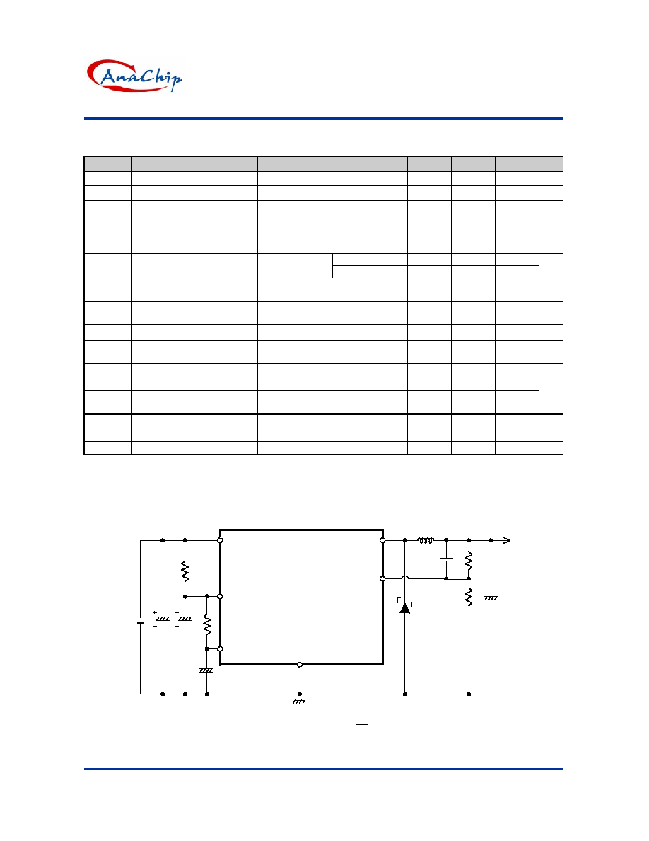
Typical Application Circuit (Continued)
2 Application with Short Circuit Protection
AP 1605
+
-
V
SS
CE
C
C
R
A
R
B
D1
V
OUT :
1.8V
FB
PV
CC
SW
V
CC
D
VCC
1N4148 for above 5V Vin and
Schottky for below 5V Vin
C
VCC
0.1uF
C
PVCC
100 uF
C
ON/OFF
0.2uF
R
ON/OFF
3.5M
R
Bias
10M
R
SENCE
1M
C
OUTPUT
100 uF
V
IN :
2.5V~7V
)
R
R
(1
Vref
Vo
B
A
+
◊
=
=~10K
Test Circuit
A
FB
Vcc
Vss
open
open
FB
Vcc
Vss
+
-
Os
c
illation
SW
SW
PVcc
PVcc
A
FB
Vcc
Vss
+
-
+
-
V
SW
PVcc
CE
CE
CE
Function Description
PWM/PFM Control (AP1605 Series)
The AP1605 consists of DC/DC converters that employ a PWM/PFM auto-switch system.
In converters of the AP1605, the PFM mode varies in a range of duty cycle from 0% to 25%, and the PWM
mode varies in a range of duty cycle from 25% to 100% according to the load current, and yet ripple voltage
produced by the switching can easily be removed through a filter because the switching frequency remains
constant. Therefore, these converters provide a low-ripple power over broad ranges of input voltage and load
current.

AP1605
PWM/PFM Dual-mode Step-Down Switching Regulator
Anachip Corp.
www.anachip.com.tw Rev. 1.1 Jan 18, 2005
5/6
Marking Information
SOP-8L/TSSOP-8L
( Top View )
Logo
Part no.
ID code: internal
Year: "01" =2001
"02" =2002
Xth week: 01~52
~
1
4
8
5
AP1605
YY WW X X
Blank : normal
L : Lead Free Package
Package Information
Package Type: SOP-8L
VIEW "A"
L
C
VIEW "A"
H
E
A
A2
A1
B
e
D
7 (4X)
0.015x45
7 (4X)
y
Dimensions In Millimeters
Dimensions In Inches
Symbol
Min.
Nom.
Max.
Min.
Nom.
Max.
A 1.40
1.60
1.75
0.055
0.063
0.069
A1 0.10
-
0.25
0.040
-
0.100
A2 1.30 1.45
1.50
0.051
0.057
0.059
B 0.33
0.41
0.51
0.013
0.016
0.020
C 0.19
0.20
0.25
0.0075
0.008
0.010
D 4.80
5.05
5.30
0.189
0.199
0.209
E 3.70
3.90
4.10
0.146
0.154
0.162
e
-
1.27
-
-
0.050
-
H 5.79
5.99
6.20
0.228
0.236
0.244
L 0.38
0.71
1.27
0.015
0.028
0.050
y
-
-
0.10
-
-
0.004
0
O
-
8
O
0
O
-
8
O