 | –≠–ª–µ–∫—Ç—Ä–æ–Ω–Ω—ã–π –∫–æ–º–ø–æ–Ω–µ–Ω—Ç: AP1702BW | –°–∫–∞—á–∞—Ç—å:  PDF PDF  ZIP ZIP |
AP1701/2/3/4
3-Pin Microprocessor Reset Circuits
This datasheet contains new product information. Anachip Corp. reserves the rights to modify the product specification without notice. No liability is assumed as a result of the use of
this product. No rights under any patent accompany the sale of the product.
Rev.1.0 May. 7, 2004
1/8
Features
- Precision Monitoring of +3V, +3.3V, and +5V
Power-Supply Voltages
- Fully Specified Over Temperature
- Available in Three Output Configurations
- Push-Pull RESET Low Output (AP1701/3)
- Push-Pull RESET High Output (AP1702/4)
- 140ms min Power-On Reset Pulse Width
- 12µA Supply Current
- Guaranteed Reset Valid to VCC = +1V
- Power Supply Transient Immunity
- No External Components
- 3-pin SOT23 package
Applications
- Computers
- Controllers
- Intelligent Instruments
- Critical µP and µC Power Monitoring
- Portable/Battery Powered Equipment
- Automotive
General Description
The AP1701/2/3/4 are used for microprocessor (µP)
supervisory circuits to monitor the power supplies in
µP and digital systems. They provide excellent
circuit reliability and low cost by eliminating external
components and adjustments when used with +5V,
+3.3V, +3.0V powered circuits.
These circuits perform a single function: they assert
a reset signal whenever the VCC supply voltage
declines below a preset threshold, keeping it
asserted for at least 140ms after VCC has risen
above the reset threshold. Reset thresholds
suitable for operation with a variety of supply
voltages are available. The AP1701/2/3/4 have
push pull outputs. The AP1701/3 have an active low
RESET output, while the AP1702/4 has an active
high RESET output. The reset comparator is
designed to ignore fast transients on VCC, and the
outputs are guaranteed to be in the correct logic
state for VCC down to 1V. Low supply current
makes the AP1701/2/3/4 ideal for use in portable
equipment. The AP1701/2/3/4 is available in a 3-pin
SOT23 package.
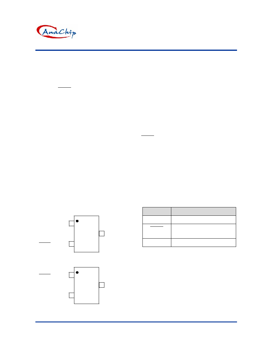
Pin Assignments
(Top View)
1
2
GND
(RESET)
V
CC
SOT-23
AP1701
AP1702
2
3
RESET
(Top View)
1
2
GND
V
CC
SOT-23
AP1703
AP1704
2
3
(RESET)
RESET
Pin Descriptions
Name
Description
GND Ground
RESET
(RESET)
Reset output pin
L: for AP1701/3
H: for AP1702/4
V
CC
Operating
voltage
input

AP1701/2/3/4
3-Pin Microprocessor Reset Circuits
Anachip Corp.
www.anachip.com.tw
Rev.1.0 May.7, 2004
2/8
Ordering Information
AP170X X X X
Enable
1: Active-Low
2: Active-High
Voltage
A: 4.63
B: 4.38
C: 4.00
D: 3.08
E: 2.93
F: 2.63
3: Active-Low
4: Active-High
Package
W:SOT23
Lead Free
Blank : Normal
L : Lead Free Package
Absolute Maximum Ratings
Symbol
Parameter
Rating
Unit
V
CC
Terminal Voltage (with respect to GND)
-0.3 to +6.0
V
V
RESET
RESET, RESET (push-pull)
-0.3 to (V
CC
+ 0.3)
V
I
CC
Input Current, V
CC
20
mA
I
O
Output Current, RESET, RESET
20 mA
V
R
Rate of Rise, V
CC
100
V/µS
P
D
Continuous Power Dissipation (T
A
= +70∞C),
de-rate 4mW/∞C above +70∞C
320 mW
T
OP
Operating Temperature Range
-40 to +105
∞C
T
ST
Storage Temperature Range
-65 to +150
∞C
T
LEAD
Lead Temperature (soldering, 10s)
+300
∞C
AP1701/2/3/4
3-Pin Microprocessor Reset Circuits
Anachip Corp.
www.anachip.com.tw
Rev.1.0 May.7, 2004
3/8
Electrical Characteristics
(T
A
=25∫C)
Symbol
Parameter
Conditions
Min.
Typ.
Max.
Unit
V
CC
V
CC
Range T
A
= 0
o
C to +70
o
C 1.0
5.5
V
V
CC
< 5.5V
19
60
µA
I
CC
Supply
Current
V
CC
< 3.6V
17
50
µA
AP1701/2/3/4A 4.54
4.63
4.72
AP1701/2/3/4B 4.29
4.38
4.47
AP1701/2/3/4C 3.92
4.00
4.08
AP1701/2/3/4D 3.02
3.08
3.14
AP1701/2/3/4E 2.87
2.93
2.99
Reset Threshold
T
A
=25∫C
AP1701/2/3/4F 2.57
2.63
2.68
V
V
TH
Reset Threshold
Tempco
30
ppm/
o
C
V
CC
to Reset Delay V
CC
= V
TH
to (V
TH
≠ 100mV)
20
µs
T
DELAY
Reset Active
Timeout Period
T
A
= 0
o
C to +70
o
C 100
240
380
ms
V
CC
= V
TH
min, I
SINK
= 1.2mA, AP1701/3
0.3
V
CC
= V
TH
min, I
SINK
= 3.2mA
0.4
V
OL
T
RESE Output
Voltage Low
V
CC
> 1.0V, I
SINK
= 50uA
0.3
V
V
CC
> V
TH
max, I
SOURCE
= 500uA,
AP1701/3
0.8V
CC
V
OH
T
RESE Output
Voltage-High
V
CC
> V
TH
max, I
SOURCE
= 800uA
V
CC
≠1.5
V
V
CC
= V
TH
max, I
SINK
= 1.2mA, AP1702/4
0.3
V
OL
RESET Output
Voltage-Low
V
CC
= V
TH
max, I
SINK
= 3.2mA
0.4
V
V
OH
RESET Output
Voltage-High
1.8V < V
CC
< V
TH
min, I
SOURCE
= 150uA,
AP1702/4
0.8 V
CC
V
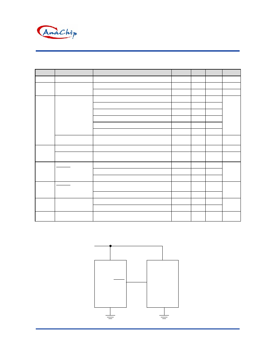
Application Circuit
AP170X
GND
RESET
(RESET)
VCC
Microprocessor
VCC
GND
RESET
INPUT
VCC

AP1701/2/3/4
3-Pin Microprocessor Reset Circuits
Anachip Corp.
www.anachip.com.tw
Rev.1.0 May.7, 2004
4/8
Function Description
A microprocessor's (µP's) reset input starts the µP
in a known state. The AP1701/2/3/4 assert reset to
prevent code-execution errors during power-up,
power-down, or brownout conditions. They assert a
reset signal whenever the VCC supply voltage
declines below a preset threshold, keeping it
asserted for at least 140ms after VCC has risen
above the reset threshold. The AP1701/2/3/4 have
a push-pull output stage.
Applications Information
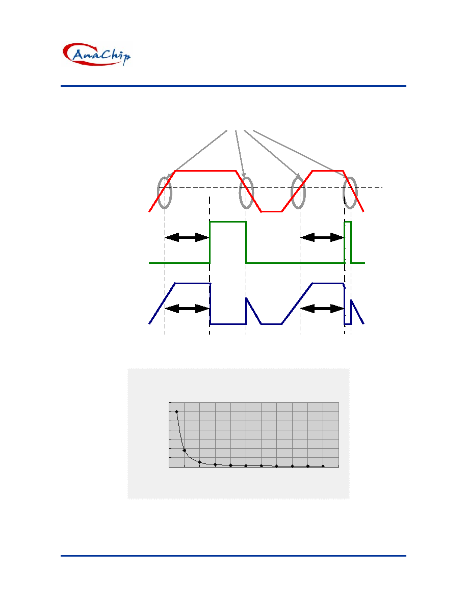
Negative-Going VCC Transients
In addition to issuing a reset to the µP during
power-up, power-down, and brownout conditions,
the AP1701/2/3/4 are relatively immune to
short-duration negative-going VCC transients
(glitches).
The AP1701/2/3/4 do not generate a reset pulse.
The graph was generated using a negative going
pulse applied to VCC, starting 0.5V above the
actual reset threshold and ending below it by the
magnitude indicated (reset comparator overdrive).
The graph indicates the maximum pulse width a
negative going VCC transient can have without
causing a reset pulse. As the magnitude of the
transient increases (goes farther below the reset
threshold), the maximum allowable pulse width
decreases. Typically, a VCC transient that goes
100mV below the reset threshold and lasts 20µs or
less will not cause a reset pulse. A 0.1µF bypass
capacitor mounted as close as possible to the VCC
pin provides additional transient immunity.
Ensuring a Valid Reset Output
Down to VCC = 0
RESET
is guaranteed to be a logic low for VCC >
1V. Once VCC exceeds the reset threshold, an
internal timer keeps RESET low for the reset
timeout period; after this interval, RESET goes
high. If a brownout condition occurs (VCC dips
below the reset threshold), RESET goes low. Any
time VCC goes below the reset threshold, the
internal timer resets to zero, and RESET goes low.
The internal timer starts after VCC returns above
the reset threshold, and RESET remains low for
the reset timeout period.
When VCC falls below 1V, the AP1701/3 RESET
output no longer sinks current--it becomes an open
circuit. Therefore, high-impedance CMOS logic
inputs connected to RESET
can drift to
undetermined voltages.
This presents no problem in most applications since
most µP and other circuitry is inoperative with VCC
below 1V. However, in applications where RESET
must be valid down to 0V, adding a pull down
resistor to RESET causes any stray leakage
currents to flow to ground, holding RESET low.
R1's value is not critical; 100k is large enough not
to load RESET and small enough to pull RESET
to ground. For the AP1702/4 if RESET is required to
remain valid for VCC < 1V.
Benefits of Highly Accurate Reset Threshold
Most µP supervisor ICs have reset threshold
voltages between 5% and 10% below the value of
nominal sup-ply voltages. This ensures a reset will
not occur within 5% of the nominal supply, but will
occur when the supply is 10% below nominal.
When using ICs rated at only the nominal supply
±5%, this leaves a zone of uncertainty where the
supply is between 5% and 10% low, and where the
reset may or may not be asserted.
AP1701/2/3/4
3-Pin Microprocessor Reset Circuits
Anachip Corp.
www.anachip.com.tw
Rev.1.0 May.7, 2004
5/8
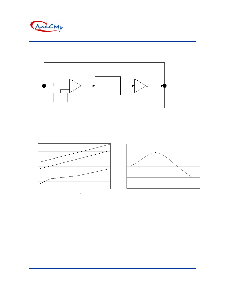
Function Block
V
REF
Delay Circuit
Driver
RESET
/ RESET
Performance Characteristics
-50 -40 -30 -20 -10 0 10 20 30 40 50 60 70 80 90 100 110 120
Iq
24
20
16
12
8
4
0
Temp ( C )
Iq v.s Temp
-40 -30 -20 -10 0 10 20 30 40 50 60 70 80 90
Threshold
Temp
2.92
2.922
2.924
2.926
2.928
Threshold v.s. Temp
AP1701/2/3/4
3-Pin Microprocessor Reset Circuits
Anachip Corp.
www.anachip.com.tw
Rev.1.0 May.7, 2004
6/8
Timing Diagram
Giltch Immunity
3000
900
270
140
90
70
58
50
50
48
48
0
500
1000
1500
2000
2500
3000
3500
0
100
200
300
400
500
600
700
800
900 1000 1100
RESET COMPARATOR OVERDRIVE(mV)
Ma
x
i
m
u
m
Tr
a
n
s
i
e
n
t
D
u
r
a
t
i
o
n(
us
)
t1 t1
t1 t1
V
CC
V
TH
Active Low
Active High

AP1701/2/3/4
3-Pin Microprocessor Reset Circuits
Anachip Corp.
www.anachip.com.tw
Rev.1.0 May.7, 2004
7/8
Marking Information
1
2
Year:0~9
Month: A~L
Identification code
( See appendix )
3
XX Y M X
(Top View)
SOT23-3L
Blank: normal
L: Lead Free Package
Appendix
Part
Number
Identification
Code
Part
Number
Identification
Code
AP1701A EA AP1703A
EG
AP1701B EB AP1703B
EH
AP1701C EC AP1703C
EI
AP1701D ED AP1703D
EJ
AP1701E EE AP1703E
EK
AP1701F EF AP1703F
EL
AP1702A E0 AP1704A
E7
AP1702B E2 AP1704B
E8
AP1702C E3 AP1704C
E9
AP1702D E4 AP1704D
EM
AP1702E E5 AP1704E
EN
AP1702F E6 AP1704F
EP

AP1701/2/3/4
3-Pin Microprocessor Reset Circuits
Anachip Corp.
www.anachip.com.tw
Rev.1.0 May.7, 2004
8/8
Package Information
Package Type: SOT23-3L
C
L
e
E
HE
D
A2
A1
b
A
Dimensions In Millimeters
Dimensions In Inches
Symbol
Min.
Nom.
Max.
Min.
Nom.
Max.
A 1.00
1.20
1.40
0.039
0.047
0.055
A1 0.00 - 0.10
0.000 - 0.004
A2 1.00
1.15
1.30
0.039
0.045
0.051
b 0.35 - 0.50
0.014
-
0.020
C
0.10 0.175 0.25 0.004 0.007 0.010
D 2.70
2.90
3.10
0.106
0.114
0.122
E 1.40
1.60
1.80
0.055
0.063
0.071
e 1.70
2.00
2.30
0.067
0.079
0.091
HE 2.40
2.70
3.00
0.094
0.106
0.118
L 0.30 - 0.55
0.012
-
0.022