
AP2004
PWM Buck Controller
This datasheet contains new product information. Anachip Corp. reserves the rights to modify the product specification without notice. No liability is assumed as a result of the use of
this product. No rights under any patent accompany the sale of the product.
Rev. 0.4 Arpr 6, 2004
1/8
Features
- PWM Buck Control Circuitry
- Operating voltage can be up to 27V
- Under voltage Lockout (UVLO) Protection
- Short Circuit Protection (SCP)
- Soft-start circuit
- Variable Oscillator Frequency -- 300Khz Max
- 1.25V voltage reference Output
- 8-pin PDIP and SOP packages
Applications
- Backlight inverter
- LCD Monitor
- XDROM, XDSL Product
- DC/DC converters in computers, etc.
General Description
The AP2004 integrates Pulse-Width-Modulation
(PWM) control circuit into a single chip, mainly
designs for power-supply regulator. All the functions
include an on-chip 1.25V reference output, an error
amplifier, an adjustable oscillator, a soft-start,
UVLO, SCP circuitry, and a push-pull output circuit.
Switching frequency is adjustable by trimming CT.
During low VCC situation, the UVLO makes sure
that the outputs are off until the internal circuit
operates normally.
Pin Assignment
1
2
3
8
7
6
5
4
OUT
GND
SCP
SS
FB
VCC
CT
COMP
( Top View )
PDIP/SOP
Pin Descriptions
Name
Description
CT Timing
Capacitor
FB Voltage
Feedback
SS Soft-Start.
COMP
Feedback Loop Compensation
OUT PWM
Output
GND Ground
VCC Supply
Voltage
SCP Short
Circuit
Protection
Ordering Information
AP2004 X X X
Package
Packing
S: SOP-8L
Blank : Tube
A : Taping
Lead Free
Blank : Normal
L : Lead Free Package
N: PDIP-8L

AP2004
PWM Buck Controller
Anachip Corp.
www.anachip.com.tw Rev. 0.4 Apr 6, 2004
2/8
Block Diagram
Bandgap
Reference
OUT
PWM Amplifier
FB
VCC
SCP
CT
Error Amplifier
COMP
UVLO
GND
0.7V
1.5V
+
-
2.5V
Internal use
1.25V
Iss
+
-
VCC
Oscillator
MAX.500KHz
SS
+
+
-
Absolute Maximum Ratings
Symbol
Parameter
Rating
Unit
V
CC
Supply voltage
28
V
V
I
Amplifier input voltage
20
V
V
O
Collector output voltage
V
CC
-1.0V
V
I
SOURCE
Source current
200 mA
I
SINK
Sink current
200 mA
T
OP
Operating temperature range
-20 to +85
o
C
T
ST
Storage temperature range
-65 to +150
o
C
T
LEAD
Lead temperature 1.6 mm(1/16 inch) from case for 10 seconds
260
o
C
AP2004
PWM Buck Controller
Anachip Corp.
www.anachip.com.tw Rev. 0.4 Apr 6, 2004
3/8
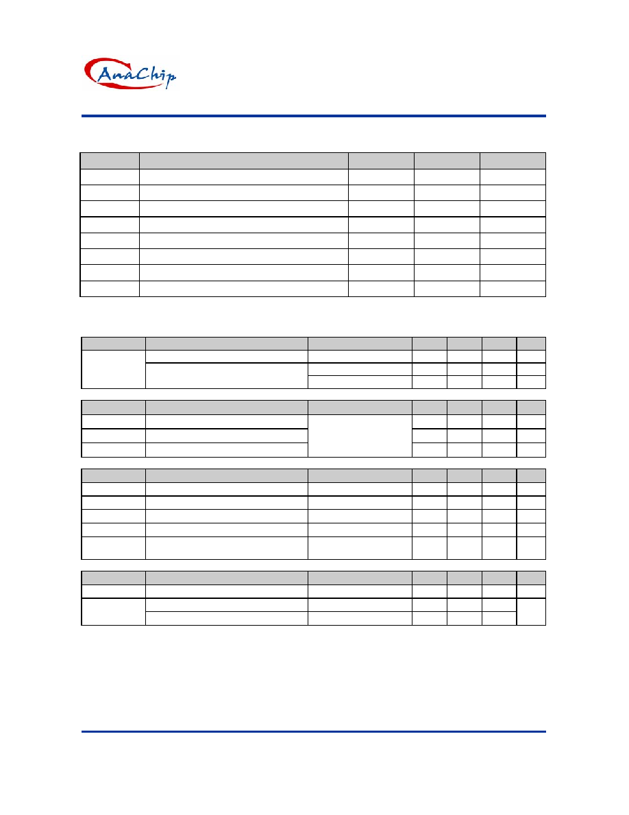
Recommended Operating Conditions
Symbol
Parameter
Min.
Max.
Unit
V
CC
Supply
voltage
3.6
27
V
V
I
Amplifier
input
voltage
1.05 1.45
V
V
O
Collector
output
voltage
Vcc-1.5 V
I
FB
Current into feedback terminal
45
�A
R
F
Feedback
resistor
100
k
C
T
Timing
capacitor
100 6800 pF
F
OSC
Oscillator
frequency
10
300
KHz
T
OP
Operating free-air temperature
-20
85
�C
Electrical Characteristics
(T
A
=25�C, V
CC
=6V, f=200 Khz)
Reference (REF)
Symbol
Parameter
Conditions
Min.
Typ.
Max.
Unit
Comp connect to FB
1.225 1.25 1.275
V
T
A
= -20�C ~ 25�C
-0.1
�1
%
V
REF
Output voltage change with
temperature
T
A
= 25�C ~ 85�C
-0.2
�1
%
Under voltage lockout (UVLO)
Symbol
Parameter
Conditions
Min.
Typ.
Max.
Unit
V
UT
Upper threshold voltage (V
CC
)
2.9
V
V
LWT
Lower threshold voltage (V
CC
)
2.4
V
V
HT
Hysteresis
(V
CC
)
I
O(REF)
= 0.1mA
T
A
= 25�C
500 mV
Short-circuit protection (SCP) control
Symbol
Parameter
Conditions
Min.
Typ.
Max.
Unit
V
IT
Input
threshold
voltage
T
A
= 25�C
0.60
0.67
0.75
V
V
STB
Standby voltage
No pull up
100
130
160
mV
V
LT
Latched input voltage
No pull up
50
100
mV
I
SCP
Input (source) current
V
I
= 0.7V, T
A
= 25�C
-10
-15
-20
�A
V
CT
Comparator threshold voltage
(COMP)
1.5
V
Oscillator (OSC)
Symbol
Parameter
Conditions
Min.
Typ.
Max.
Unit
F
OSC
Frequency
C
T
=270 pF
200
KHz
Standard deviation of frequency
C
T
=270 pF
10
F
OSC
Frequency change with voltage
V
CC
=3.6V
~
20V
1
%

AP2004
PWM Buck Controller
Anachip Corp.
www.anachip.com.tw Rev. 0.4 Apr 6, 2004
4/8
Electrical Characteristics (Continued)
(T
A
=25�C, V
CC
=6V, f=200 Khz)
Error-amplifier
Symbol
Parameter
Conditions
Min.
Typ.
Max.
Unit
V
IO
Input
offset
voltage
V
O
(FB)=1.25V
�6
mV
I
IO
Input
offset
current
V
O
(FB)=1.25V
�100
nA
I
IB
Input bias current
V
O
(FB)=1.25V
160
500
nA
V
CM
Common-mode input voltage
range
V
CC
=3.6V ~ 20V
1.05
1.45
V
AV
Open-loop voltage
amplification
R
F
=200 k 70
80
dB
GBW Unity-gain
bandwidth
1.5 MHz
CMRR
Common-mode rejection ratio
60
80
dB
V
OH
Max. output voltage
V
ref
-0.1
V
V
OL
Min. output voltage
1
V
I
OI
Output (sink) current (COMP) V
ID
= -0.1V, V
O
= 1.25V
0.5
1.6
mA
I
OO
Output (source) current
(COMP)
V
ID
= 0.1V, V
O
= 1.25V
-45
-70
�A
Output section
Symbol
Parameter
Conditions
Min.
Typ.
Max.
Unit
I
LEAK
Leakage
current
V
O
= 25V
10
�A
Sink current
V
IN
= 20V
200
mA
I
DRV
Source current
V
IN
= 20V
200
mA
V
SAT
Output saturation voltage
I
O
= 10 mA
1.0
1.5
V
I
SC
Short-circuit output current
V
O
= 6V
120
mA
PWM comparator
Symbol
Parameter
Conditions
Min.
Typ.
Max.
Unit
V
T0
CT
0.6
0.7
V
V
T100
Input threshold voltage at f =
10 KHz (COMP)
Maximum duty cycle
1.2
1.3
V
Total device
Symbol
Parameter
Conditions
Min.
Typ.
Max.
Unit
I
CCA
Average
supply
current C
T
= 270pF
6
10
mA
Soft Start
Symbol
Parameter
Conditions
Min.
Typ.
Max.
Unit
V
SS
Soft-start
Voltage
2.3 V
I
SS
Constant Charge Current
20
�A

AP2004
PWM Buck Controller
Anachip Corp.
www.anachip.com.tw Rev. 0.4 Apr 6, 2004
5/8
Typical Application Circuit
L1
33uH
R1
R2
C3
470uF
Output
Step-Down DC/DC converter
C2
10nF
Optional
Vcc = 12V
P mos
Q1
1
2
3
8
7
6
5
4
OUT
FB
VC
C
COMP
GN
D
SCP
SS
CT
C6 220nF
C5 50nF
C4 270pF
9K
3K
C1
470uF
5A
R3 10K~100K
C4
50nF
Optional
Typical Characteristics
REFERENCE OUTPUT VOLTAGE
v.s.
POWER-SUPPLY VOLTAGE
1.22
1.225
1.23
1.235
1.24
1.245
1.25
1.255
1.26
4
8
12
16
20
24
28
Vcc-Power Supply Voltage (V)
Vref-
Reference
Output Volta
g
e
(V)
AVERAGE SUPPLY CURRENT
v.s.
POWER-SUPPLY VOLTAGE
0
1
2
3
4
5
0
4
8
12
16
20
24
28
Vcc - Power-Supply Voltgae (V)
Icc-Average
Supply Current
(mA)
AVERAGE SUPPLY CURRENT
v.s.
AMBIENT TEMPERATRUE
2
3
4
5
6
7
-50
-25
0
25
50
75
100
T
A
- Ambient Temperatrure()
I
CC
- Aver
age
Suppl
y Cur
r
e
nt
(mA)
V
CT
v.s. Frequency
0
0.2
0.4
0.6
0.8
1
1.2
1.4
1.6
0
100
200
300
Frequency (KHz)
V
CT
(V)
VCT(min)
VCT(max)