
AP2007
Synchronous PWM Controller
This datasheet contains new product information. Anachip Corp. reserves the rights to modify the product specification without notice. No liability is assumed as a result of the use of
this product. No rights under any patent accompany the sale of the product.
Rev. 1.0 Apr 1, 2005
1/7
Features
- Single 4.5V to 20V Supply Application
- 0.8V + 2.0% Voltage Reference
- Virtual Frequency Control
TM
- Fast Transient Response
- Synchronous Operation for High Efficiency (93%)
- Short Circuit Protect
- Small Size with Minimum External Components
- Soft Start and Enable Functions
- Under Voltage Lockout Function
- SOP-8L Pb-Free Package
Applications
- Microprocessor Core Supply
- Low Cost Synchronous Applications
- Voltage Regulator Modules (VRM)
- Networking Power Supplies
- Sequenced Power Supplies
- Telecommunication Power Supplies.
General Description
The AP2007 is a low-cost, full featured, synchronous
voltage-mode controller designed for use in single
ended power supply applications where efficiency is
of primary concern. Synchronous operation allows
for the elimination of heat sinks in many applications.
The AP2007 is ideal for implementing DC/DC
converters needed to power advanced
microprocessors in low cost systems or in distributed
power applications where efficiency is important.
High-side drive circuitry, and preset shoot-thru
control, allows the use of inexpensive
1P+1N-channel power switches.
AP2007's features include temperature
compensated voltage reference,
Virtual Frequency
Control
TM
method to reduce external component count,
an internal 200KHz virtual frequency oscillator,
under-voltage lockout protection, soft-start,
shutdown function and current sense comparator
circuitry.
Virtual Frequency Control is a trademark of
PWRTEK, LLC.
Pin Assignments
SOP-8L
1
(Top View)
VCC
V
REF
PHASE
DRVP
DRVN
FB
GND
AP2007
2
3
4
5
6
7
8
SS/SHDN
Ordering Information
AP2007 X X
Package
Packing
S: SOP-8L
Blank : Tube
A : Taping
Pin Descriptions
Name
Description
VCC Chip
supply
voltage
V
REF
Reference
voltage
PHASE
Input from the phase node between
the MOSFETs
DRVP
High side driver output (P MOSFET)
GND Ground
DRVN
Low side driver output (N MOSFET)
FB Feedback
input
SS/ SHDN
Soft start, a capacitor to ground sets
the slow start time / Shutdown
function
AP2007
Synchronous PWM Controller
Anachip Corp
www.anachip.com.tw Rev. 1.0 Apr 1, 2005
2/7
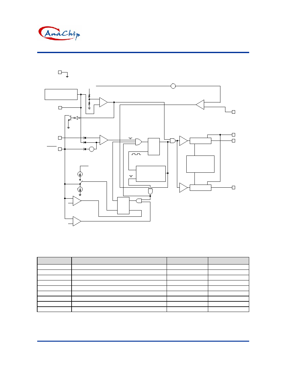
Block Diagram
CROSS
CURRENT
CONTROL
DRVN
VIRTUAL FREQ
OSCILLATOR
DRVP
R Q
S
Q S
QB R
+
-
+
-
+
-
+
-
VOLTAGE
REFERENCE
+
-
VCC
0.8V
UNDER
VOLTAGE
ERROR
COMP
VCC
12ua
2ua
0.2V
0.9V
SS/SHDN
FB
GND
OCSET
PHASE
VCC
DRVP
DRVN
AP2007 FUNCTIONAL BLOCK DIAGRAM
Virtual Frequency Control - Patent
Number 6,456,050.
V
REF
-
+
0.4V
-
+
0.4V
Absolute Maximum Ratings
Symbol
Parameter
Range.
Unit
V
IN
VCC to GND
-1 to 22
V
V
PHASE
PHASE to GND
-1 to 22
V
V
DRVP
DRVP to GND
-1 to 22
V
V
DRVN
DRVN to GND
-1 to 22
V
JC
Thermal Resistance Junction to Case
90
o
C/W
JA
Thermal Resistance Junction to Ambient
250
o
C/W
T
OP
Operating Temperature Range
-40 to +85
o
C
T
ST
Storage Temperature Range
-65 to +150
o
C
T
LEAD
Lead Temperature (Soldering) 10 Sec.
300
o
C
AP2007
Synchronous PWM Controller
Anachip Corp
www.anachip.com.tw Rev. 1.0 Apr 1, 2005
3/7
Electrical Characteristics
Unless specified: V
CC
=12V; GND = 0V;V
O
= 5V; T
J
= 25
o
C
Symbol
Parameter
Conditions
Min.
Typ.
Max.
Unit
Power Supply
V
CC
Supply Voltage
(Recommended)
4.5
-
20
V
I
CC
Supply Current
DRVP & DRVN are floating
-
9.5
-
mA
V
LINE
Line
Regulation
V
O
= 2.5V
-
0.5
%
Error Comparator
A
OL
Gain
(A
OL
)
-
70
-
dB
I
B
Input
Bias
- 0.2 1 uA
Oscillator
F
OSC
Oscillator
Frequency
- 200 - KHz
DC
MAX
Oscillator Max Duty Cycle
80
85
-
%
Mofset Drivers
I
DRVP
DRVP
Source/Sink
V
CC
� V
DRVP
=3V
V
DRVP
� V
GND
= 2V
0.5 1 - A
I
DRVN
DRVN
Source/Sink
V
CC
� V
DRVN
= 3V
V
DRVL
� V
GND
= 2V
0.5 1 - A
V
DRVL
DRVP/N Low Level Voltage
-
-
1.2
V
V
DRVH
DRVP/N High Level Voltage
V
CC
-1.2
- - V
Protection
T
DEAD
Dead Time
DRVP & DRVN are floating
-
150
-
nS
Vocset Over Current Setting Voltage
0.4
V
V
DRVP/N
DRVP/DRVN System Error
Voltage (Note3)
V
SS
=Low, V
CC
3.8,
over current happen
V
CC
-1.2
- - V
Reference
Reference Voltage
0.784
0.8
0.816
V
V
REF
Accuracy
0
o
C to 70
o
C
-2 - +
2
%
Soft Start
I
SSC
Charge
Current
V
SS
= 1.5V
8.0
10
12
uA
I
SSD
Discharge
Current
V
SS
= 1.5V
1.3
2
2.7
uA
Under voltage lockout (UVLO)
V
UT
Upper Threshold Voltage (V
CC
)
-
4.0
-
V
V
LWT
Lower
Threshold
Voltage
(V
CC
)
-
3.8
-
V
V
HT
Hysteresis
(V
CC
)
- 200 - mV
Note 1. Specification refers to Typical Application Circuit.
Note 2. This device is ESD sensitive. Use of standard ESD handling precautions is required.
Note 3. Abnormal condition; Ex: over-current, under-voltage lockout, soft-start disappear.
AP2007
Synchronous PWM Controller
Anachip Corp
www.anachip.com.tw Rev. 1.0 Apr 1, 2005
4/7
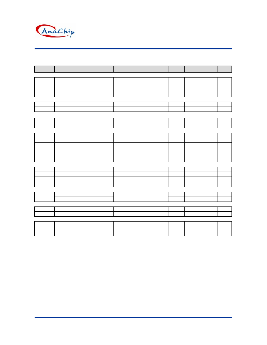
Typical Application Circuit
8
7
6
5
1
2
3
4
D1
Option
VCC
SS/SHDN
FB
DRVP
GND
PHASE
DRVN
Q1
Q2
L1
10uH
C8
470u/16V
C9
Vout=3.2V*
+
-
Vin
+
-
C1
R2
1K
R3
3K*
* Vout = 0.8 x (1+R3/R2)
AP2007
C4
330n
C3
330n
R1
12
V
REF
10n
470u/16V
470u/16V
AF9435
C5
AF9410
C2
0.1u
C6
47n
C7
0.1u
1 Option
1 Option
R2 1K ~ 10K
(4835)
(4412)
Virtual Frequency Control
Virtual Frequency Control
combines the
advantages of constant frequency and constant
off-time control in a single mode of operation. This
allows fix frequency, precision switching voltage
regulator control with fast transient response and
the smallest solution size. Switch duty cycle can be
adjusted from 0% to 100% on a pulse by pulse basis
when responding to transient conditions. Both 0%
and 100% duty cycle operation can be maintained
for extended periods of time in response to load or
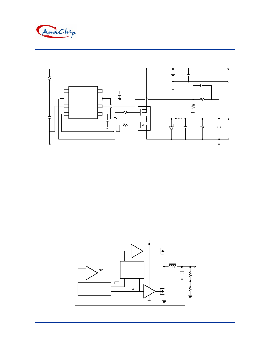
line transients. Figure 1 depicts a simplified
operation of the Virtual Frequency Control
technique: The VFC oscillator generates a pulse of
a known duration (VFC_Pulse). The regulator loop
responds by returning a complementary feedback
pulse (FB_Pulse). The FB_Pulse duration is a result
of external conditions such as inductor size, the
voltage across the inductor and the duration of the
VFC_Pulse. A VFC control loop is then formed
whereby the duration of the VFC_Pulse is modified
as a result of the FB_Pulse duration. The VFC loop
arrives at a state of equilibrium, where the operating
frequency remains inherently constant.
GATE
CONTROL
LOGIC
VIRTUAL FREQ
OSCILLATOR
+
-
FB Pulse
VFC Pulse
Vref
ERROR
COMP
V
IN
Lout
Cout
Vout
Rfb1
Rfb2
Figure 1: Virtual Frequency Control Loop-
Synchronous single supply application.

AP2007
Synchronous PWM with VFC Controller (Preliminary)
Anachip Corp
www.anachip.com.tw Rev. 1.0 Apr 1, 2005
5/7
Virtual Frequency Control (Continued)
Virtual frequency control is a technique that
provides stable, constant frequency of operation for
pulse controlled architectures such as constant
off-time/on-time. This is all done internal to the IC
with minimal number of components and without the
need for connections to external terminals such as
input and/or output. No external compensation is
required, thus providing a low cost, high
performance fix frequency solution for switching
voltage regulators.
Virtual Frequency Control is a trademark of
PWRTEK, LLC.
Function Description
Synchronous Buck Converter
Primary V
CORE
power is provided by a synchronous,
voltage-mode pulse width modulated (PWM)
controller. This section has all the features required
to build a high efficiency synchronous buck
converter, including soft-start, shutdown, and
cycle-by-cycle current limit.
Referring to the functional block diagram FIG 1, the
output voltage of the synchronous converter is set
and controlled by the output of the error comparator.
The external resistive divider reference voltage, is
derived from an internal trimmed-bandgap voltage
reference. The inverting input of the error
comparator receives its voltage from the FB pin.
The internal oscillator uses an on-chip capacitor and
trimmed precision current sources to set the virtual
oscillation frequency to 200KHz. The virtual
frequency oscillator sets the PWM latch. This pulls
DRVN low, turning off the low-side N_MOSFET and
DRVP is pulled low, turning on the high-side
P-MOSFET (once the cross-current control allows
it). The triangular voltage ramp at the FB pin is then
compared against the reference voltage at the
inverting input of the error comparator. When the FB
voltage increases above the reference voltage, the
comparator output goes high. This pulls DRVP high,
turning off the high-side P-MOSFET, and DRVN is
pulled high, turning on the low-side N-MOSFET
(once the cross-current control allows it). The Virtual
Frequency Oscillator then generates a programmed
off time to allow the FB voltage to return to the valley
voltage of the triangular ramp. At the end of the off
time the PWM latch is set and the cycle repeats
again.
Under Voltage Lockout
The under voltage lockout circuit of the AP2007
assures that the high-side P-MOSFET driver
outputs remain in the off state whenever the supply
voltage drops below set parameters. Lockout occurs
if V
CC
falls below 3.8V. Normal operation resumes
once V
CC
rises above 4.0V.
R
DS(ON)
Current Limiting
The current limit threshold (0.4V) is set by
connecting an internal resistor from the V
CC
supply
to OCSET. Vocset is compared to the voltage at the
PHASE node. This comparison is made only when
the high-side drive is high to avoid false current limit
triggering due to uncontributing measurements from
the MOSFETs off-voltage. When the voltage at
PHASE is less than the voltage at OCSET, an
over-current condition occurs and the soft start cycle
is initiated. The synchronous switch
turns on and SS/ SHDN starts to sink 2uA. When
SS/ SHDN reaches 0.2V, it then starts to source
10uA and a new cycle begins. When the soft start
voltage is below 0.9V the cycle is controlled with
pulse by pulse current limiting.
Soft Start
Initially, SS/ SHDN pin sources 10uA of current to
charge an external capacitor. The inverting input of
the error comparator is clamped to a voltage
proportional to the voltage on SS/ SHDN . This limits
the on-time of the high-side P-MOSFET, thus
leading to a controlled ramp-up of the output
voltages.