AP436
Synchronous Rectifier MOSFET Driver
This datasheet contains new product information. Anachip Corp. reserves the rights to modify the product specification without notice. No liability is assumed as a result of the use of
this product. No rights under any patent accompany the sale of the product.
Rev.1.0 Oct 4, 2005
1/6
Features
- V
OUT
slew-rate minimum 100V/uS @ CL=3000pF
- I
OUT
(sink & source)=1.2 / 0.9 A
- Safety considered.
- Reduce power system thermal & increase
system efficiency.
- Pb-free packages: SOT89-5L, SOP-8L
Application
- Power Adapter.
50~120W for LCD Monitor & NB...etc.
General Descriptions
The AP436 is a high-speed controller designed to
drive N-channel power MOSFET used as
synchronous rectifiers in high current, high
frequency fly-back converters. The circuit does
not require any ties to the primary side and
derives its operating power directly from the
secondary. The circuit functions are structured by
anticipating transformer output transitions then
turns the power MOSFET on or off before the
transitions of the transformer to minimize body
drain diode conduction and reduce associated
losses.
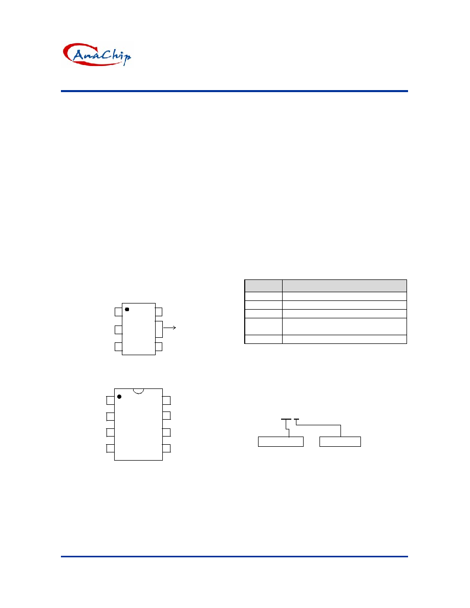
Pin Assignment
( Top View )
1
2
3
74
5
GND
SOT89-5L
AP436
TAB
(GND)
V
DC
V
R
V
CC
V
OUT
1
2
3
4
7
6
5
V
DC
GND
GND
V
R
V
OUT
SOP-8L
AP436
( Top View )
GND
V
CC
GND
8
Pin Descriptions
Name
Description
V
CC
Operating voltage input
V
R
Reference
input
voltage
V
DC
Duty
cycle
input
voltage
V
OUT
Output voltage for driving N channel
MOSFET
GND Ground
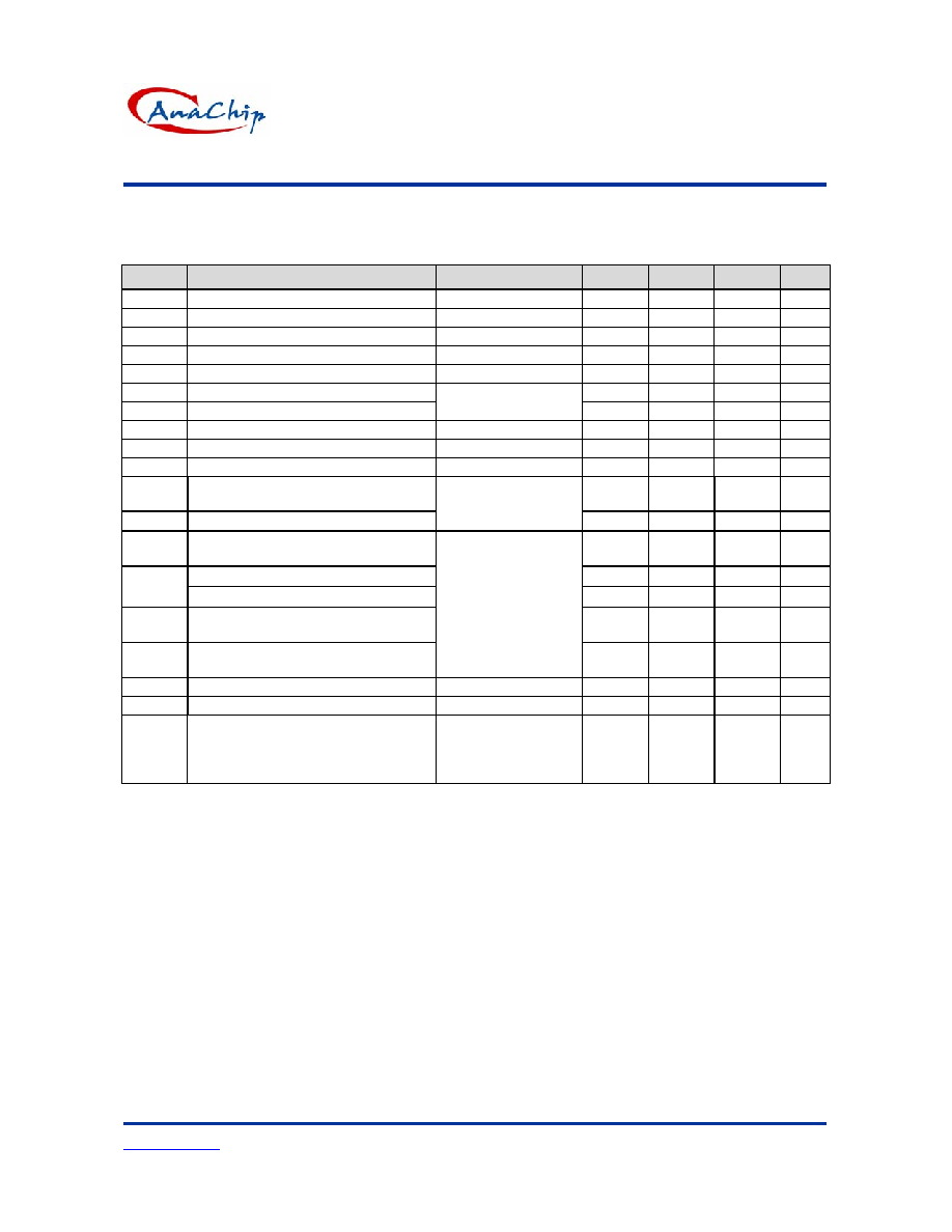
Ordering Information
S : SOP-8L
Y : SOT89-5L
Packing
Blank: Tube
A : Taping
Package
AP436 XX X

AP436
Synchronous Rectifier MOSFET Driver
Anachip Corp.
www.anachip.com.tw
Rev.1.0 Oct 4, 2005
2/6
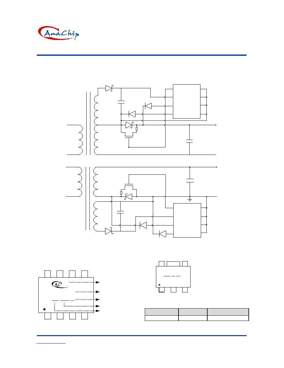
Block Diagrams
V
DC
I
B2
V
R
Start-Up
Buffer
15K
V
OUT
V
CC
GND
5.6V
High
Speed
Comparator
Block
I
B1
Absolute Maximum Ratings
Symbol
Parameter
Rating
Unit
V
CC
Supply
Voltage
14
V
V
R
Reference
input
voltage
-0.3V2.5
V
V
DC
Duty cycle input voltage
-0.3VV
CC
-2.1
V
V
OUT
Output voltage to Ground
-0.7
V
P
D
Power
dissipation
1
W
T
ST
Storage temperature range
-65 to 150
o
C
T
OP
Operating temperature range
-40 to +125
o
C
V
OP
Operating voltage range
7.2 to 14
V
AP436
Synchronous Rectifier MOSFET Driver
Anachip Corp.
www.anachip.com.tw
Rev.1.0 Oct 4, 2005
3/6
Electrical Characteristics
Unless otherwise specified, guaranteed for Tj=25
O
C, V
CC
=12V.
Symbol
Parameter
Conditions
Min.
Typ.
Max.
Units
V
CC
Supply
Voltage
7.2
12
14
V
I
B1
Input Bias Current (Pin V
R
) V
R
=0.7V,V
CC
=12V -74 -103
-150
uA
I
B2
Input Bias Current (Pin V
DC
) V
DC
=0.7V,V
CC
=12V -74 -103 -150 uA
V
R
Reference Pin Voltage Range
0.3
0.7
1.5
V
V
DCL
Minimum
Input
Signal
Voltage
-0.3
V
V
OH
Output
High
Vcc-1.5
V
V
OL
Output
Low
CL=3000pF
R
L
=2K
0.8
0.9
V
V
DC
Detection
Voltage
V
R
V
R
+6 mV
V
CM
Common
Mode
Range
0.7
1.5
V
I
S
Supply Current (Average Value)
V
CC
=12V,No Load
5.5
6
mA
I
SOURCE
Sourcing Current (Transient Value)
1250
mA
I
SINK
Sinking
Current
(Transient
Value)
V
CC
=12V,C
L
=3000pF
R
L
=2K,Cin=47uF,
F
Vdc
=200KHz
900 mA
I
OP
Operation Current (Average Value)
14
mA
Output Delay Time(Low to High)
80
100
nS
T
PD
Output Delay Time(High to Low)
60
100
nS
T
R
Output Rise Time (10% ~ 90% Rise
Edge)
35 100 nS
T
F
Output Fall Time (10% ~ 90% Fall
Edge)
V
CC
=12V,C
L
=3000pF
R
L
=2K,Cin=47uF,
F
Vdc
=60KHz
60 100 nS
F
OP
Maximum
Operation
Frequency
200 KHz
P
D
Power Dissipation
SOT89-5L, SOP-8L
1
W
I
SD
(Icc
Shutdown
Current)
V
CC
=5V,
C
L
=3000pF
R
L
=2K,Cin=47uF,
F
Vdc
=60KHz
0.2
0.43
mA
AP436
Synchronous Rectifier MOSFET Driver
Anachip Corp.
www.anachip.com.tw
Rev.1.0 Oct 4, 2005
4/6
Typical Application Circuit
1
S
D
SYSTEM
OUTPUT
G
IRF
Z44N
1N5819
220u
with
0.1u
AP436
GND
GND
GND
GND
BEAD
1N4148
1N4148
+
-
+
-
V
OUT
V
DC
V
CC
V
R
2
S
D
SYSTEM
OUTPUT
G
IRF
Z44N
1N5819
BEAD
1N4148
1N4148
+
-
+
-
220u
with
0.1u
AP436
GND
GND
GND
GND
V
OUT
V
DC
V
CC
V
R
Marking Information
(1)
SOP-8L
( Top View )
Logo
Part Number
ID code: internal
Year: "01" =2001
"02" =2002
Xth week: 01~52
~
1
4
8
5
AP436
YY WW X
(2)
SOT89-5L
7
1
2
3
4
5
XX Y M
XX : Identification code
(See Appendix)
Y : Year: 0-9
M : Month: A~L
(Top View)
Appendix
Part Number
Package
Identification Code
AP436 SOT89-5L
FM
AP436
Synchronous Rectifier MOSFET Driver
Anachip Corp.
www.anachip.com.tw
Rev.1.0 Oct 4, 2005
5/6
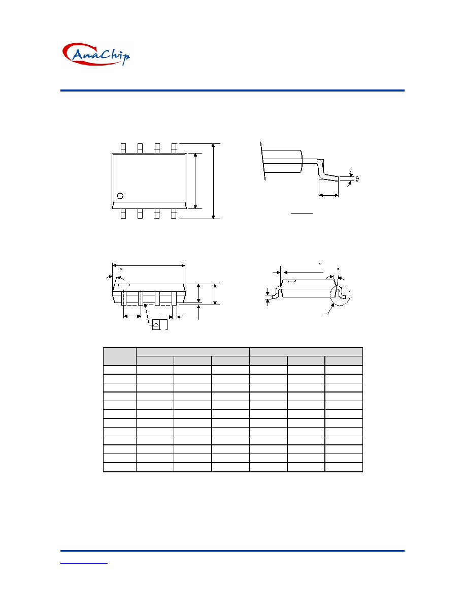
Package Information
(1) Package Type: SOP-8L
VIEW "A"
L
C
VIEW "A"
H
E
A
A2
A1
B
e
D
7 (4X)
0.015x45
7 (4X)
y
Dimensions In Millimeters
Dimensions In Inches
Symbol
Min.
Nom.
Max.
Min.
Nom.
Max.
A 1.40 1.60 1.75
0.055
0.063
0.069
A1 0.10 - 0.25 0.040 - 0.100
A2 1.30 1.45 1.50 0.051
0.057
0.059
B 0.33 0.41 0.51
0.013
0.016
0.020
C 0.19 0.20 0.25
0.0075
0.008
0.010
D 4.80 5.05 5.30 0.189
0.199
0.209
E 3.70 3.90 4.10
0.146
0.154
0.161
e - 1.27 - -
0.050
-
H 5.79 5.99 6.20 0.228
0.236
0.244
L 0.38 0.71 1.27
0.015
0.028
0.050
y - - 0.10 - -
0.004
0
O
- 8
O
0
O
- 8
O