AP450
2 Channel Linear Controller with Enable Function
This datasheet contains new product information. Anachip Corp. reserves the rights to modify the product specification without notice. No liability is assumed as a result of the use of
this product. No rights under any patent accompany the sale of the product.
Rev. 1.1 Sep 7, 2004
1/6
Features
- 2 Channel Linear Control Circuitries
- Operating voltage can be up to 20V
- Under voltage Lockout (UVLO) Protection
- Current Limit
- Over Voltage Protection
- Power Good Function
- 1.25V/0.8V internal voltage reference
- 8-pin PDIP and SOP Pb-Free packages
Applications
- Backlight inverter
- LCD Monitor
- XDROM, XDSL Product
General Description
The AP450 series integrates two channel linear
controllers into a single chip, mainly designs for
power-supply regulator. All the functions included
an on-chip 1.25V/0.8V reference output, error
amplifier, UVLO, current limit. During low VCC
situation, the UVLO makes sure that the outputs
are off until the internal circuit is operational
normally.
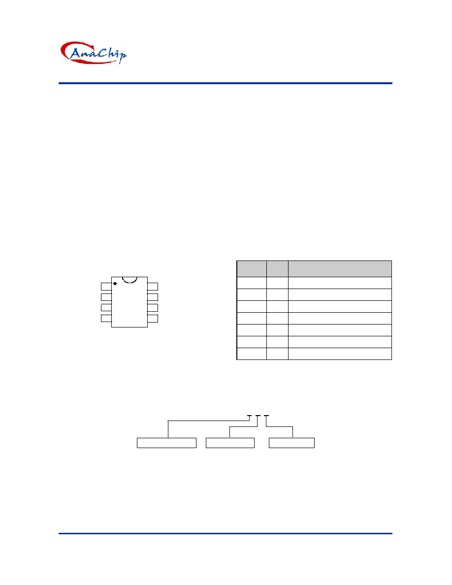
Pin Assignment
SOP-8L/PDIP-8L
1
2
3
4
5
6
7
8
(Top View)
EN1/2
FB1
AP450
OUT1
FB2
OUT2
V
REF
GND
Vcc
Pin Descriptions
Pin
Name
Pin
No.
Description
GND 1 Signal
Ground
EN1/2
2
Channel 1/2 Enable Pin
OUT1
3
Linear Controller CH1output
FB1, 2
4, 5
Voltage Feedback
OUT2
6
Linear Controller CH2 output
V
REF
7 1.25V/0.8V
Output
Vcc 8
Supply
Voltage
Ordering Information
AP450 X X X
Package
Packing
N: PDIP-8L
S: SOP-8L
Blank: Tube
A : Taping
Bandgap Version
A: 1.25V
BG
B: 0.8V
BG
AP450
2 Channel Linear Controller with Enable Function
Anachip Corp.
www.anachip.com.tw Rev. 1.1 Sep 7, 2004
2/6
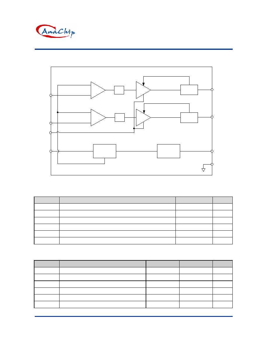
Block Diagram
Bandgap
Reference
Amp
+
_
Current
Limit
Buffer
LPF
Amp
+
_
Buffer
LPF
EN1/2
FB2
FB1
GND
OUT1
OUT2
Current
Limit
UVLO
Vcc
1.25V/0.8V
2.5V
V
REF
Absolute Maximum Ratings
Symbol
Parameter
Rating
Unit
V
CC
Supply voltage
22
V
V
I
Amplifier input voltage
20
V
V
O1
/ V
O2
CH1 / CH1Linear driver voltage to ground
-0.3V20
V
T
OP
Operating temperature range
-20 to +85
o
C
T
ST
Storage temperature range
-65 to +150
o
C
T
LEAD
Lead temperature 1.6 mm(1/16 inch) from case for 10 seconds
260
o
C
Recommended Operating Conditions
Symbol
Parameter
Min.
Max.
Unit
V
CC
Supply
voltage
3.6
20
V
V
I
Amplifier
input
voltage
1.05
1.45 V
V
O1
/ V
O2
CH1 / CH2 Linear driver voltage to ground
-
Vcc-1.5
V
I
FB
Current into feedback terminal
-
45
�A
R
F
Feedback
resistor
100
-
k
T
OP
Operating free-air temperature
-20
85
�C

AP450
2 Channel Linear Controller with Enable Function
Anachip Corp.
www.anachip.com.tw Rev. 1.1 Sep 7, 2004
3/6
Electrical Characteristics
(T
A
=25�C, V
CC
=6V)
Reference (REF)
Symbol
Parameter
Conditions
Min.
Typ.
Max.
Unit
AP450A 1.225
1.25
1.275
V
O1
/ V
O2
connect to FB1 / FB2
AP450B
0.784 0.800 0.816
V
T
A
= -20�C ~ 25�C
-
-0.1
�1
%
V
OUT1/2
Output voltage change with
temperature
T
A
= 25�C ~ 85�C
-
-0.2
�1
%
Under voltage lockout (UVLO)
V
UT
Upper threshold voltage (V
CC
) -
2.9
-
V
V
LWT
Lower threshold voltage (V
CC
) -
2.4
-
V
V
HT
Hysteresis
(V
CC
)
I
O(REF)
= 0.1mA
T
A
= 25�C
- 500 - mV
Output section
I
CL1
CH1
Current
Limit
V
CC
=5V, V
NOUT2
=V
FB2
=0V 25 - - mA
I
CL2
CH2
Current
Limit
V
CC
=5V, V
NOUT3
=V
FB3
=0V 25 - - mA
Enable function
V
IL
Low (regulator ON)
-
0.6
V
V
IH
EN pin logic input threshold
voltage for EN1/2
High (regulator OFF)
2.0
1.3
- V
I
IL
Low (regulator ON)
-
-0.03
-
�A
I
IH
EN pin logic input current for
EN1/2
High (regulator OFF)
-
0.3
-
�A
Total device
I
CCA
Average supply current
-
5
7
mA
Thermal Resistor
SOP8 -
90
-
O
C/W
JA
Thermal Resistor
Junction to Ambient
PDIP8 -
60
-
O
C/W
Typical Application Circuit
1
2
3
4
GND
Vcc
8
7
6
5
EN1/2
FB1
FB2
OUT1
OUT2
V
REF
Vcc=12V
OFF ON
V
OUT
3=1.8V
270
220�F
3.3V
3.3V
220
390
180
V
OUT
2=2.5V
0.1�F
220�F
220�F
AP450B

AP450
2 Channel Linear Controller with Enable Function
Anachip Corp.
www.anachip.com.tw Rev. 1.1 Sep 7, 2004
4/6
Typical Characteristics
REFERENCE OUTPUT VOLTAGE
v.s.
POWER-SUPPLY VOLTAGE
0.795
0.7975
0.8
0.8025
0.805
4
6
8
10
12
14
16
18
20
Vcc-Power Supply Voltage (V)
Vref- Refer
e
n
c
e
Ou
t
p
u
t
Vo
lt
a
g
e
(V)
AVERAGE SUPPLY CURRENT
v.s.
POWER-SUPPLY VOLTAGE
0
1
2
3
4
5
0
4
8
12
16
20
Vcc - Power-Supply Voltgae (V)
I
cc-
A
v
er
age
Su
pp
l
y
C
u
rrent
(mA
)
AVERAGE SUPPLY CURRENT
v.s.
AMBIENT TEMPERATRUE
2
3
4
5
6
7
-50
-25
0
25
50
75
100
T
A
- Ambient Temperatrure()
I
CC
-
A
verage
Su
pp
ly C
u
r
r
ent
(mA)
Marking Information
(Top View)
SOP-8L/PDIP-8L
AP450 X
YY WW X
Logo
Part No.
ID code: internal
Year: "01" =2001
"02" =2002
Xth week: 01~52
~
5
8
4
1
Bandgap version
A: 1.25V
BG
B: 0.8V
BG

AP450
2 Channel Linear Controller with Enable Function
Anachip Corp.
www.anachip.com.tw Rev. 1.1 Sep 7, 2004
5/6
Package Information
(1) PDIP-8L (Plastic Dual-in-line Package )
E1
D
7 (4X)
A
L
A2
A1
B2
B1
B
e
S
15 (4X)
E
C
eB
E-PIN O0.118 inch
PIN #1 INDENT O0.025 DEEP 0.006-0.008 inch
Dimensions in millimeters
Dimensions in inches
Symbol
Min.
Nom.
Max.
Min.
Nom.
Max.
A - - 5.33 - - 0.210
A1 0.38 -
- 0.015 -
-
A2 3.1 3.30 3.5 0.122
0.130
0.138
B 0.36 0.46 0.56 0.014 0.018
0.022
B1 1.4 1.52 1.65 0.055 0.060 0.065
B2 0.81 0.99 1.14 0.032 0.039
0.045
C 0.20 0.25 0.36 0.008 0.010 0.014
D 9.02 9.27 9.53 0.355 0.365
0.375
E 7.62 7.94 8.26 0.300 0.313
0.325
E1 6.15 6.35 6.55 0.242 0.250
0.258
e - 2.54 - - 0.100 -
L 2.92 3.3 3.81 0.115
0.130
0.150
eB 8.38 8.89 9.40 0.330 0.350 0.370
S 0.71 0.84 0.97 0.028 0.033
0.038