Single Hall Effect Switch
ATS137
This datasheet contains new product information. Anachip Corp. reserves the rights to modify the product specification without notice. No liability is assumed as a result of the use of
this product. No rights under any patent accompany the sale of the product.
Rev.A5 Jul 14, 2004
1/7
ATC
Features
- 3.5V to 20V DC operation voltage
- Temperature compensation
- Wide operating voltage range
- Open-Collector pre-driver
- 25mA maximum sinking output current.
- Reverse Polarity Protection
Applications
- VCD/DVD loader, CD/DVD ROM
- Cover detector
- Speed measurement
- Home appliances
- Home safety
General Description
ATS137 is an switched Hall-Effect IC which is for
contactless switching applications. The device
includes an on-chip Hall voltage generator for
magnetic sensing, an amplifier that amplifies the
Hall voltage, a schmitt trigger to provide switching
hysteresis for noise rejection, and an open-collector
output. The bandgap regulator allows a wide
operating voltage range.
ATS137 is rated for operating temperature range
from -20
�C to 85�C and voltage range from 3.5V to
20V.
Ordering Information
ATS137 X
X X - X
Packing
Blank : Tube or Bulk
A : Tape & Reel
P: SIP3
W: SOT23
Package
Lead
L : Lead Free
Blank: Normal
Wafer Body
Blank or
A~Z : if necessary
to specify
Single Hall-effect Switch
- X
Magnetic
Characteristics
A or B
Typical Circuit
ATS
137
3.5V ~20V
Digital Output
Vcc
DO
Vss
L
R
Single Hall Effect Switch
ATS137
Anachip Corp.
www.anachip.com.tw
Rev. A5 Jul 14, 2004
2/7
ATC
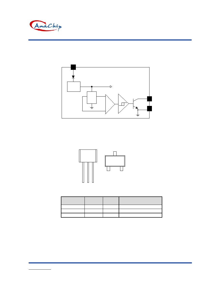
Functional Block Diagrams
Regulator
Hall
plate
Amp
1
3
2
Vcc
Vss
DO
Pin Descriptions
137
1
2 : Vss
3 : DO
2 3
137
1
2
3
1 : Vcc
Top view
Name
P/I/O
Pin #
Description
Vcc
P
1
Positive Power Supply
Vss P
2
Ground
DO O
3
Digital
Output

Single Hall Effect Switch
ATS137
Anachip Corp.
www.anachip.com.tw
Rev. A5 Jul 14, 2004
3/7
ATC
Absolute Maximum Ratings
( at Ta=25
o
C )
Characteristics
Symbol
Values
Unit
Supply voltage
V
CC
20 V
Reverse Vcc Polarity Voltage
V
RCC
-20 V
Magnetic flux density
B
Unlimited
Output OFF Voltage
Vce
30
V
Output "on" current
Continuous
Ic
25
mA
Operating temperature
Ta
-20~+85
�C
Storage temperature
Ts
-65~+150
�C
Maximum Junction Temp.
Tj
175
�C
SIP-3L 400
mW
Package Power
Dissipation
SOT23-3L
Pd
200 mW
Electrical Characteristics
(Ta=+ 25
�C)
Characteristic
Symbol
Test Conditions
Min
Typ
Max
Units
Supply voltage
Vcc
--
3.5
-
20
V
Output saturation voltage
Vce(sat)
Vcc=14V, Ic=20mA
-
300
700
mV
Output leakage current
Icex
Vce=14V, Vcc=14V
-
<0.1
10 uA
Supply current
Icc
Vcc=20V, Output Open
-
5
10
mA
Output rise time
tr
Vcc=14V, RL=820
,
CL=20pF
- 0.3 1.5 us
Output falling time
tf
Vcc=14V, RL=820
,
CL=20pF
- 0.3 1.5 us
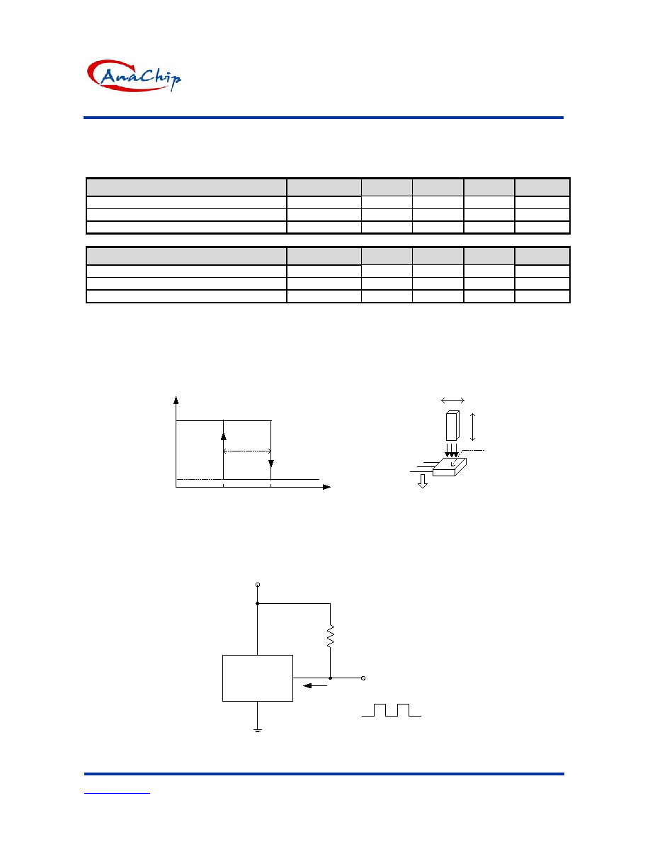
Test Circuit
CL
14V
DO
RL=820 Ohm
CL=20 pF
RL
Test Circuit
Single Hall Effect Switch
ATS137
Anachip Corp.
www.anachip.com.tw
Rev. A5 Jul 14, 2004
4/7
ATC
Magnetic Characteristics (Ta=25
o
C)
(1mT=10Gauss)
A grade
Parameter
Symbol
Min.
Typ.
Max.
Unit
Operate Point
Bop
-
-
100
Gauss
Release point
Brp
10
-
-
Gauss
Hysteresis Bhys
-
80
-
Gauss
B grade
Parameter
Symbol
Min.
Typ.
Max.
Unit
Operate Point
Bop
-
-
130
Gauss
Release point
Brp
10
-
-
Gauss
Hysteresis Bhys
-
80
-
Gauss
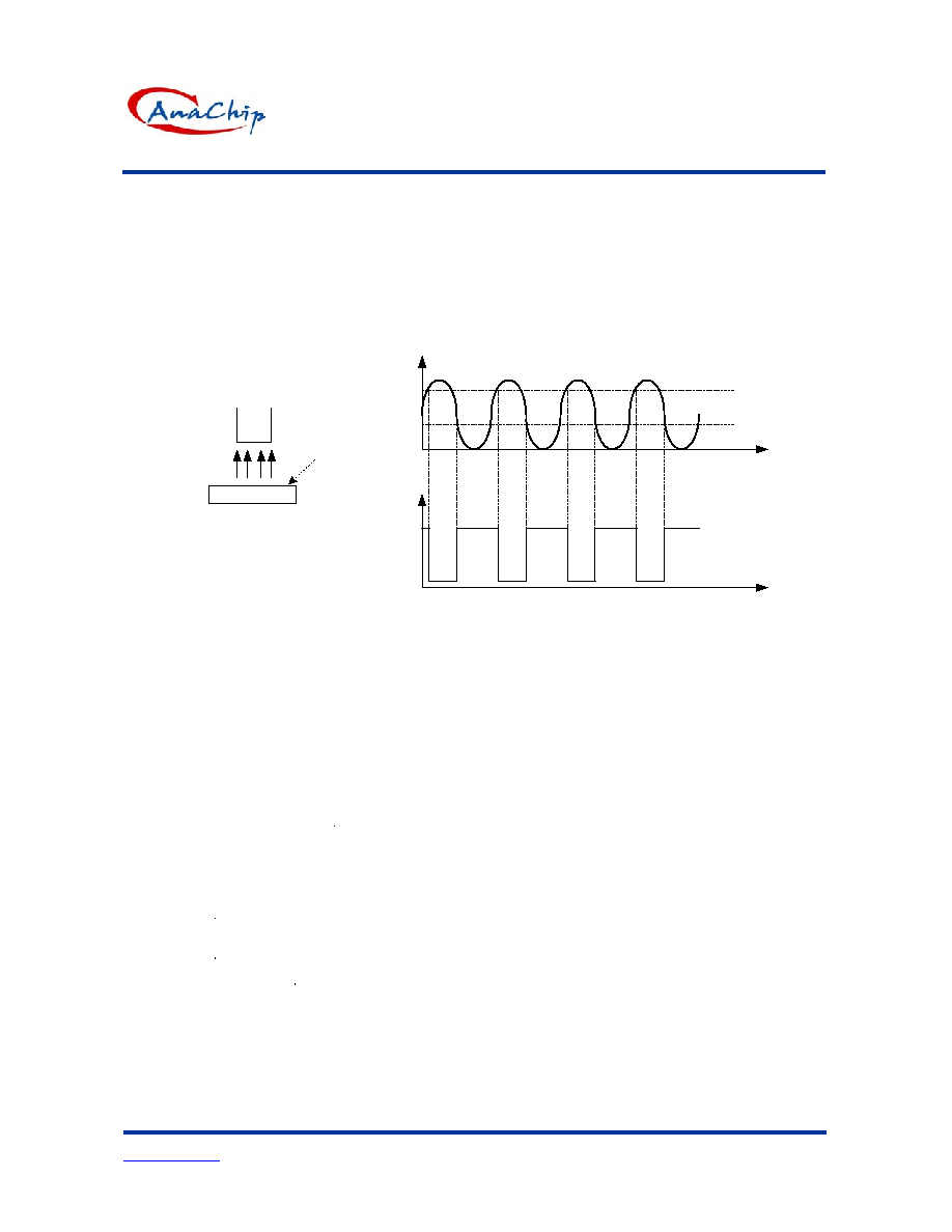
Application Information
-Operating principle
ATS137 is a three pins Hall Effect switch IC which can turn magnetic flux variety to digital output signal. In
other words, it is an interface from magnetic system to electrical one by Hall effect. The illustrations are shown
in Fig.1.
Vo
Vce(sat)
Vcc
magnetic flux
(Gauss)
Turn on
Turn off
hys
B
op
B
rp
B
Magnet
electrical
S
Marking
side
Fig.1 Hall-effect switch
Output driver is open-collector topology and maximum sink current (I
sink
) is 25mA. The illustrated circuit is
shown as Fig.2.
ATS
137S
3.5V ~20V
Digital Output
Vcc
DO
Vss
Vo
L
R
sink
I
Fig.2 Application circuit
Single Hall Effect Switch
ATS137
Anachip Corp.
www.anachip.com.tw
Rev. A5 Jul 14, 2004
5/7
ATC
Application Information (Continued)
Vo will turn on(low) if the S magnetic flux larger than operation point (Bop), and turns off whenever the
magnetic flux is removed and lower than release point (Brp). The related waveforms are shown in Fig.3.
Bop
Brp
Vce(sat)
Vcc
Vo
magnetic flux (mT)
t
t
S
Hall Effect switch
Marking side
Fig.3 Vo and magnetic flux variety
The major applications are for contactless switching and shown as follows:
-
VCD/DVD loader, CD/DVD ROM: Detect if the tray is opened or closed
-
Cover detector (open/close): Cellular phone cover detector, Refrigerator door detector, Microwave oven
door sensor... etc
-
Home safety: instead of reed relay to detect the situation of door/window.
-
Due to contactless and without mechanical contact point, its reliability and life cycle are much longer than
reed relay. In addition, its switching speed is much faster than mechanical devices.