
ACU50752S3C
CATV/TV/Cable Modem Upconverter MMIC
Advanced Product Information
Rev. 0
FEATURES
Integrated Monolithic Upconverter
Compatible with all digital and analog modulation types
5 Volt Operation
Low Power Consumption
Low Noise Figure
High Conversion Gain
Low Distortion
Excellent Oscillator Purity and Phase Noise
Remote Shutdown Feature
Small Size
Low Cost
High Reliability
DESCRIPTION
The ACU50752 is a Monolithic GaAs IC designed to perform
the upconverter functions in a double conversion tuner: gain
block, local oscillator and balanced mixer. The
specifications meet the requirements of CATV, TV and
Cable Modem applications. Supplied in a 16-lead SOIC
package and requiring only a single polarity 5 V supply (or
3.5 V, with slightly reduced performance), the IC is well
suited in situations where small size, low cost, low auxiliary
parts count and a no-compromise performance is important.
It provides tuner manufacturers the opportunity to reduce
cost by lowering the component count and decreasing the
amount of labor-intensive production alignment steps, while
significantly improving performance and reliability.
ABSOLUTE MAXIMUM RATINGS
S3C
16 Pin SOIC Package
PARAMETER
ABSOLUTE MAXIMUM
V
DD
/V
IF
/V
OSC
(Pins 1,10,14,& 16)
9
V
DC
V
RF
/V
TUNE
(Pins 6 & 11)*
0
V
DC
RF Input Voltage
+60
dBmV
Storage Temperature
- 55 to +200
�C
Soldering Temperature
260
�C
Soldering Time
5
Sec.
Operating Case Temperature
- 40 to + 85
�C
PHASE
8
5
6
7
SPLITTER
OSC
2
3
4
1
MXR
9
12
11
10
15
14
13
16
LOW NOISE
AMP
R
IN
+90
- 90
IF
1,
+V
DD
GND
GND
RF
IN
GND
GND*
V
DD
LO
T
CKT
GND
OSC
OUT
GND
IF
2
, +V
DD
Shut Down/
Current Adjust
Inductor
* Varactor return. Do not connect to common ground
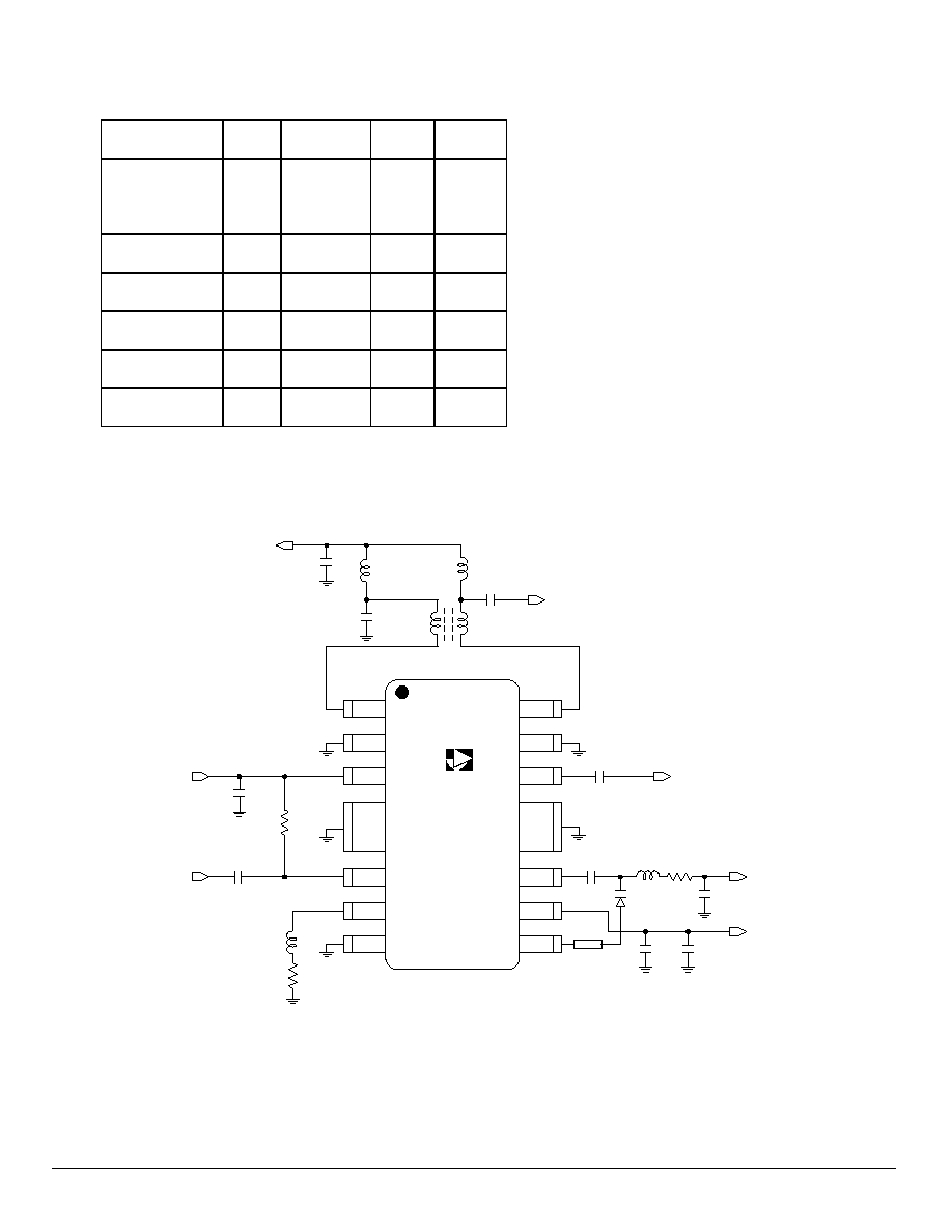
FUNCTIONAL BLOCK DIAGRAM
A
2
A
ACU50752S3C
ACU 50
752
0.01 uF
100 pF
3.3 uH
3.3 uH
BALUN
1:1
100 pF
IF
OUT
shut down/ *
current adjust
0.01 uF
0.01 uF
RF
IN
3.3uH
0.01 uF
330 uF
TAN
5 V
DC
(V
DD
Osc.)
Tuning Voltage
.01 uF
68 nH 47
ISV245
9.1 pF
100 pF
OSC OUT
(To prescaler)
1
2
3
4
5
6
7
8
16
15
14
13
12
11
10
9
5 V
DC
(V
DD
Mixer)
L
RI
RG
NOTES:
L
=
Printed inductor
RG
=
Gain control/impedance match resistor (240W for 8 dB gain)
RI
=
Current adjust resistor (2.7W for 60 mA mixer current)
*
=
Apply -2V DC for shutdown, 0< VDC < 0.3 for 60 mA mixer current
OPERATING RANGES
PARAMETER
MIN.
TYPICAL
MAX.
UNITS
Frequency
RF
IF
LO
50
900
950
860
1200
2060
MHz
V
TUNE
1.5
27
Volts
V
DDIF
4.75
5
5.25
Volts
V
DDLO
4.75
5
5.25
Volts
I
DDIF
58
80
mA
I
DDLO
60
80
mA

3
A
ELECTRICAL SPECIFICATIONS
(Packaged Unit, T
A
= 25
o
C, V
DDIF
/V, V
DDLO
=+ 5V, RF = 50 to 860 MHz, IF = 1170 MHz)
PARAMETER
MIN.
TYP.
MAX.
UNIT
Conversion Gain
1
5.0
8.0
-
dB
Gain Flatness
1
-
1.0
-
dB
SSB Noise Figure
1
-
6.5
8.0
dB
CSO
2
-
-60
-57
dBc
CTB
2
-
-60
-57
dBc
Cross Modulation
3
-
-62
-60
dBc
2-Tone 2nd Order Input IP
4
-
40
-
dBm
2-Tone 3rd Order Input IP
4
-
18
-
dBm
LO Phase Noise
5
-
-84
-81
dBc/Hz
LO Power to Prescaler
-10
-5
-
dBm
LO to RF Leakage
-
-22
-
dBm
LO to IF Leakage
-
-24
-
dBm
RF to IF Isolation
40
50
-
dB
Tuning Voltage
1
1.0
-
22
V
Shutdown Voltage(Pin 3)
-
-2
-
V
V
DDIF
4.75
5.0
5.25
V
V
DDLO
4.75
5.0
5.25
V
I
DDIF
58
80
mA
I
DDLO
60
80
mA
Power Consumption
600
800
mW
Notes:
1. As measured in ANADIGICS test fixture
2. 128 Channels @ + 7 dBmV
3. 128 Channels, 99 % Modulation @ 15 KHz
4. Two tones @ -15 dBm each
5. At 10 KHz offset
ACU50752S3C

4
ANADIGICS, Inc.
35 Technology Drive
Warren, New Jersey 07059
Tel: (908) 668-5000 / Fax: (908) 668-5132
Email: Mkg@anadigics.com
www.anadigics.com
IMPORTANT NOTICE
ANADIGICS, Inc. reserves the right to make changes to its products or discontinue any product at any time without notice. The Advanced Product
data sheets and product specifications contained in this data sheet are subject to change prior to a products formal introduction. The information in
this data sheet has been carefully checked and is assumed to be reliable. However, ANADIGICS assumes no repsponsibility for inaccuracies.
ANADIGICS strongly urges customers to verift that the informationn they are using is current before placing orders.
WARNING
ANADIGICS products are not intened for use in life support appliances, device, or systems. Use of an ANADIGICS product in any such
application without written consent is prohibited.
A
0.244
0.158
0.050
0.068
0.020
0.040
0.006
BASE PLANE
SEATING PLANE
0.394
0.016
0.010
0.386
0.152
0.229
0.065
0.054
BSC
0.064
0.013
0.010
0.004
8
7
6
5
3
2
1
4
16
15
14
13
12
11
10
9
PACKAGE OUTLINE