
08/2001
ACU50752
CATV/TV/Cable Modem Upconverter
MMIC
Data Sheet - Rev 2.0
Figure 1: Functional Block Diagram
FEATURES
∑
Integrated Monolithic Upconverter
∑
Compatible with all digital and analog
modulation types
∑
5 Volt Operation
∑
Low Power Consumption
∑
Low Noise Figure
∑
High Conversion Gain
∑
Low Distortion
∑
Excellent Oscillator Purity and Phase Noise
∑
Remote Shutdown Feature
∑
Small Size
∑
Low Cost
∑
High Reliability
PRODUCT DESCRIPTION
S3 Package
Modified 16 Pin SOIC
The ACU50752 is a Monolithic GaAs IC designed to
perform the upconverter functions in a double
conversion tuner: gain block, local oscillator and
balanced mixer. The specifications meet the
requirements of CATV, TV and Cable Modem
applications. Offered in a modified 16-lead SOIC
package and requiring only a single polarity 5 V supply
(or 3.5 V, with slightly reduced performance), the IC
is well suited for applications where small size, low
cost, low auxiliary parts count and a no-compromise
performance is important. It provides tuner
manufacturers the opportunity to reduce cost by
lowering the component count and decreasing the
amount of labor-intensive production alignment
steps, while significantly improving performance and
reliability.
PHASE
8
5
6
7
SPLITTER
OSC
2
3
4
1
MXR
9
12
11
10
15
14
13
16
LOW NOISE
AMP
R
IN
+90
- 90
IF
1,
+V
D D
GND
GND
RF
I N
GND
GND*
V
D DLO
T
CKT
GND
OSC
OUT
GND
IF
2
, +V
D D
Shut Down/
Current Adjust
Inductor
* Varactor return. Do not connect to common ground

2
ACU50752
Data Sheet - Rev 2.0
08/2001
PIN
NAME
DESCRIPTION
PIN
NAME
DESCRIPTION
1
IF
1
, V
DDIF
Balanced IFoutput and
supply
9
VC
RTN
Varactor return
2
GND
Ground
10
V
DDLO
Oscillator supply
3
V
BIAS
Shut down/current adjust
11
Tank
Oscillator tank circuit
4
GND
Ground
12
GND
Ground
5
GND
Ground
13
GND
Ground
6
RF
IN
RFInput
14
OSC
OUT
Oscillator output to
Prescalar
7
I
BIAS
Current Bias
15
GND
Ground
8
GND
Ground
16
IF
2
, V
DDIF
Balanced IF output and
supply
Table 1: Pin Description

Data Sheet - Rev 2.0
08/2001
3
ACU50752
ELECTRICAL CHARACTERISTICS
Table 2: Absolute Minimum and Maximum Ratings
Table 3: Operating Ranges
The device may be operated safely over these conditions; however, parametric
performance is guaranteed only over the conditions defined in the electrical
specifications.
Stresses in excess of the absolute ratings may cause permanent damage.
Functional operation is not implied under these conditions. Exposure to absolute
ratings for extended periods of time may adversely affect reliability.
PARAMETER
MIN
MAX
UNIT
V
DDIF
,V
DDLO
,V
OSC
(Pins 1,10,14 & 16)
0
9
VDC
V
RF
/V
TUNE
(Pins 6 & 11)
-
0
VDC
RF Input Voltage
-
+60
dBmV
Storage Temperature
- 55
+200
∞C
Soldering Temperature
-
260
∞C
Soldering Time
-
5
Sec.
PARAMETER
MIN
TYP
MAX
UNIT
Frequency
RF
IF
LO
50
900
950
-
-
-
860
1200
2060
MHz
V
DDIF
4.75
5
5.25
VDC
V
DDLO
4.75
5
5.25
VDC
Shutdown Voltage (Pin 3)
-
-2
-
V
Tuning Voltage
1.5
-
27
V
Operating Case Temperature
-40
-
+85
O
C

4
ACU50752
Data Sheet - Rev 2.0
08/2001
Table 4: Electrical Specifications
(T
A
= 25
o
C; V
DDIF
, V
DDLO
=+ 5V; RF = 50 to 860 MHz; IF = 1170 MHz)
Notes:
(1) As measured in ANADIGICS test fixture
(2) 128 Channels @ + 7 dBmV
(3) 128 Channels, 99 % Modulation @ 15 KHz
(4) Two tones @ -15 dBm each
(5) At 10 KHz offset
PARAMETER
MIN
TYP
MAX
UNIT
Conversion Gain
(1)
5.0
8.0
-
dB
Gain Flatness
(1)
-
1.0
-
dB
SSB Noise Figure
(1)
-
6.5
8.0
dB
CSO
(2)
-
-60
-57
dBc
CTB
(2)
-
-60
-57
dBc
Cross Modulation
(3)
-
-62
-60
dBc
2-Tone 2nd Order Input IP
(4)
-
40
-
dBm
2-Tone 3rd Order Input IP
(4)
-
18
-
dBm
LO Phase Noise
(5)
-
-84
-81
dBc/Hz
LO Power to Prescaler
-10
-5
-
dBm
LO to RF Leakage
-
-22
-
dBm
LO to IF Leakage
-
-24
-
dBm
RF to IF Isolation
40
50
-
dB
Tuning Voltage
(1)
1.0
-
22
V
I
DDIF
-
58
80
mA
I
DDLO
-
60
80
mA
Power Consumption
-
600
800
mW

Data Sheet - Rev 2.0
08/2001
5
ACU50752
*
ACU 50752
0.01 uF
100 pF
3.3 uH
3.3 uH
BALUN
1:1
100 pF
IF
OUT
shut down/ *
current adjust
0.01 uF
0.01 uF
RF
IN
3.3uH
0.01 uF
330 uF
TAN
5 V
DC
(V
DD
Osc.)
Vtune
.1 uF
68 nH
51
ISV245
9.1 pF
100 pF
OSC OUT
(To prescaler)
1
2
3
4
5
6
7
8
1 6
1 5
1 4
1 3
1 2
1 1
1 0
9
5 V
DC
(V
DD
Mixer)
L
R I
RG
12K
0.01
µ
F
Notes:
L
=
Printed inductor (2~3 nH)
RG
=
Gain control/impedance match resistor (240
for 8 dB gain)
RI
=
Current adjust resistor (2.7 W for 60 mA mixer current)
*
=
Apply -2 V DC for shutdown, 0< VDC < 0.3 for 60 mA mixer current
Figure 2: Test Circuit Schematic
6
ACU50752
Data Sheet - Rev 2.0
08/2001
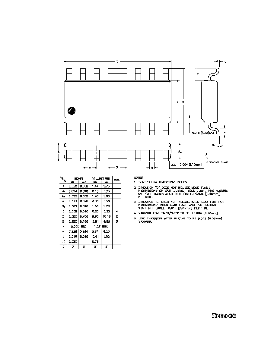
PACKAGE OUTLINE
Figure 3: S3 Package Outline - Modified 16 Pin SOIC

Data Sheet - Rev 2.0
08/2001
7
ACU50752
NOTES

WARNING
ANADIGICS products are not intended for use in life support appliances, devices or systems. Use of an ANADIGICS
product in any such application without written consent is prohibited.
IMPORTANT NOTICE
ANADIGICS, Inc.
141 Mount Bethel Road
Warren, New Jersey 07059, U.S.A.
Tel: +1 (908) 668-5000
Fax: +1 (908) 668-5132
URL: http://www.anadigics.com
E-mail: Mktg@anadigics.com
ANADIGICS, Inc. reserves the right to make changes to its products or to discontinue any product at any time without
notice. The product specifications contained in Advanced Product Information sheets and Preliminary Data Sheets are
subject to change prior to a product's formal introduction. Information in Data Sheets have been carefully checked and are
assumed to be reliable; however, ANADIGICS assumes no responsibilities for inaccuracies. ANADIGICS strongly urges
customers to verify that the information they are using is current before placing orders.
Data Sheet - Rev 2.0
08/2001
8
ACU50752
ORDERING INFORMATION
ORDER NUMBER
TEMPERATURE
RANGE
PACKAGE
DESCRIPTION
COMPONENT PACKAGING
ACU50752S3CTR
-40∞C to +85∞C
Modified 16 Pin
SOIC
Tape & Reel, 3500 pieces per reel
ACU50752S3C
-40∞C to +85∞C
Modified16 Pin
SOIC
Tube, 50 pieces per tube