General Description
The AAT2512 is a member of AnalogicTech's Total
Power Management ICTM (TPMICTM) product fam-
ily. It is a dual channel synchronous buck convert-
er operating with an input voltage range of 2.7V to
5.5V, making it ideal for applications with single-
cell lithium-ion/polymer batteries.
Both regulators have independent input and
enable pins. Offered with fixed or adjustable out-
put voltages, each channel is designed to operate
with 27µA (typical) of quiescent current, allowing
for high efficiency under light load conditions.
The AAT2512 requires only three external compo-
nents (C
IN
, C
OUT
, and L
X
) for each converter, mini-
mizing cost and real estate. Both channels are
designed to deliver 400mA of load current and
operate with a switching frequency of 1.4MHz,
reducing the size of external components.
The AAT2512 is available in a Pb-free, 12-pin
TDFN33 package and is rated over the -40∞C to
+85∞C temperature range.
Features
∑
V
IN
Range: 2.7V to 5.5V
∑
Output Current:
-- Channel 1: 400mA
-- Channel 2: 400mA
∑
98% Efficient Step-Down Converter
∑
Integrated Power Switches
∑
100% Duty Cycle
∑
1.4MHz Switching Frequency
∑
Internal Soft Start
∑
150µs Typical Turn-On Time
∑
Over-Temperature Protection
∑
Current Limit Protection
∑
Available in TDFN33-12 Package
∑
-40∞C to +85∞C Temperature Range
Applications
∑
Cellular Phones
∑
Digital Cameras
∑
Handheld Instruments
∑
Microprocessor / DSP Core/ IO Power
∑
PDAs and Handheld Computers
AAT2512
Dual 400mA High Frequency Buck Converter
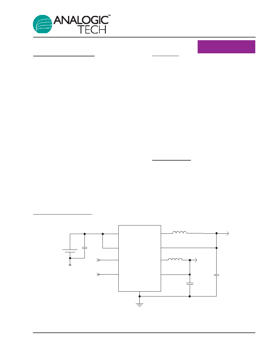
Typical Application
AAT2512
4.7µF
GND
LX1
FB1
VIN1
VIN2
V
BAT
C
IN
EN1
EN2
L1
4.7µH
L2
4.7µH
C
OUT
4.7µF
V
OUT1
LX2
FB2
V
OUT2
2512.2006.06.1.4
1
SystemPower
TM
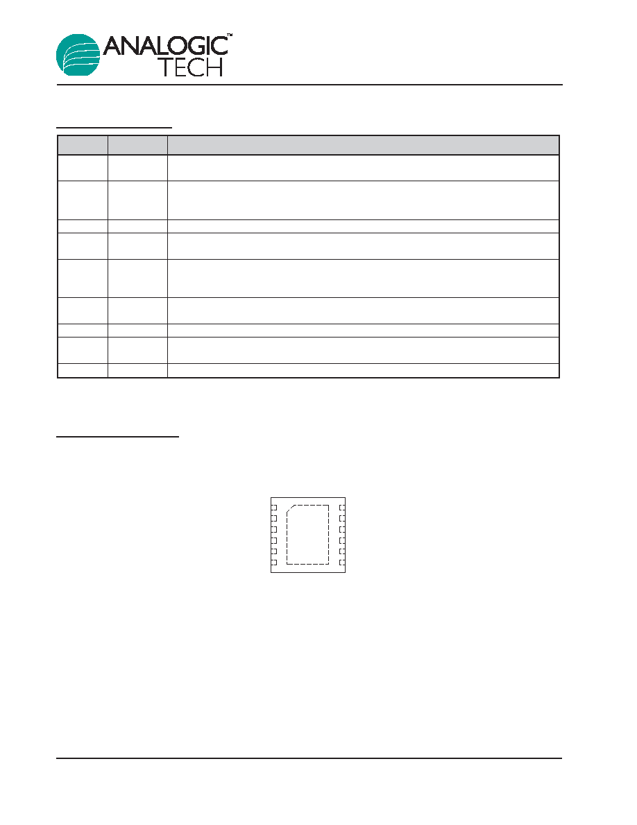
Pin Descriptions
Pin Configuration
TDFN33-12
(Top View)
EN1
FB1
GND
1
EN2
FB2
GND
VIN1
LX1
GND
VIN2
LX2
GND
2
3
4
5
6
12
11
10
9
8
7
Pin #
Symbol
Function
1
EN1
Enable pin for Channel 1. When connected low, it disables the channel and consumes
less than 1µA of current. When connected high, normal operation.
2
FB1
Feedback input pin for Channel 1. This pin is connected to the converter output. It is used
to see the output of the converter to regulate to the desired value via an external resistor
divider.
3, 6, 7, 10
GND
Ground.
4
EN2
Enable pin for Channel 2. When connected low, it disables the channel and consumes
less than 1µA of current. When connected high, normal operation.
5
FB2
Feedback input pin for Channel 2. This pin is connected to the converter output. It is used
to see the output of the converter to regulate to the desired value via an external resistor
divider.
8
LX2
Power switching node for Channel 2. Output switching node that connects to the output
inductor.
9
VIN2
Input supply voltage for Channel 2. Must be closely decoupled.
11
LX1
Power switching node for Channel 2. Output switching node that connects to the output
inductor.
12
VIN1
Input supply voltage for Channel 1. Must be closely decoupled.
AAT2512
Dual 400mA High Frequency Buck Converter
2
2512.2006.06.1.4
Absolute Maximum Ratings
1
Thermal Information
Symbol
Description
Value
Units
P
D
Maximum Power Dissipation
2.0
W
JA
Thermal Resistance
2
50
∞C/W
Symbol
Description
Value
Units
V
IN
Input Voltages to GND
6.0
V
V
LX
LX to GND
-0.3 to V
P
+ 0.3
V
V
FB
FB1 and FB2 to GND
-0.3 to V
P
+ 0.3
V
V
EN
EN1 and EN2 to GND
-0.3 to 6.0
V
T
J
Operating Junction Temperature Range
-40 to 150
∞C
T
LEAD
Maximum Soldering Temperature (at leads, 10 sec)
300
∞C
AAT2512
Dual 400mA High Frequency Buck Converter
2512.2006.06.1.4
3
1. Stresses above those listed in Absolute Maximum Ratings may cause permanent damage to the device. Functional operation at condi-
tions other than the operating conditions specified is not implied. Only one Absolute Maximum Rating should be applied at any one time.
2. Mounted on an FR4 board.
Electrical Characteristics
1
V
IN
= 3.6V; T
A
= -40∞C to +85∞C, unless otherwise noted. Typical values are T
A
= 25∞C.
Symbol
Description
Conditions
Min
Typ
Max Units
V
IN
Input Voltage
2.7
5.5
V
V
OUT
Output Voltage Tolerance
I
OUT
= 0 to 400mA;
V
IN
= 2.7V to 5.5V
-3.0
3.0
%
V
OUT
Output Voltage Range
0.6
V
IN
V
I
Q
Quiescent Current
Per Channel
27
70
µA
I
SHDN
Shutdown Current
EN1 = EN2 = GND
1.0
µA
I
LX_LEAK
LX Leakage Current
V
IN
= 5.5V, V
LX
= 0 to V
IN
1.0
µA
I
FB
Feedback Leakage
V
FB
= 1.0V
0.2
µA
I
LIM
P-Channel Current Limit
Both Channels
1.2
A
R
DS(ON)H
High Side Switch On Resistance
0.45
R
DS(ON)L
Low Side Switch On Resistance
0.40
V
LINE
Line Regulation
V
IN
= 2.7V to 5.5V
0.2
%
F
OSC
Oscillator Frequency
1.4
MHz
T
S
Start-Up Time
From Enable to Output Regulation;
150
µs
Both Channels
T
SD
Over-Temperature Shutdown
140
∞C
Threshold
T
HYS
Over-Temperature Shutdown
15
∞C
Hysteresis
V
EN(L)
Enable Threshold Low
0.6
V
V
EN(H)
Enable Threshold High
1.4
V
I
EN
Input Low Current
V
IN
= V
FB
= 5.5V
-1.0
1.0
µA
AAT2512
Dual 400mA High Frequency Buck Converter
4
2512.2006.06.1.4
1. The AAT2512 is guaranteed to meet performance specifications over the -40∞C to +85∞C operating temperature range and is assured
by design, characterization, and correlation with statistical process controls.
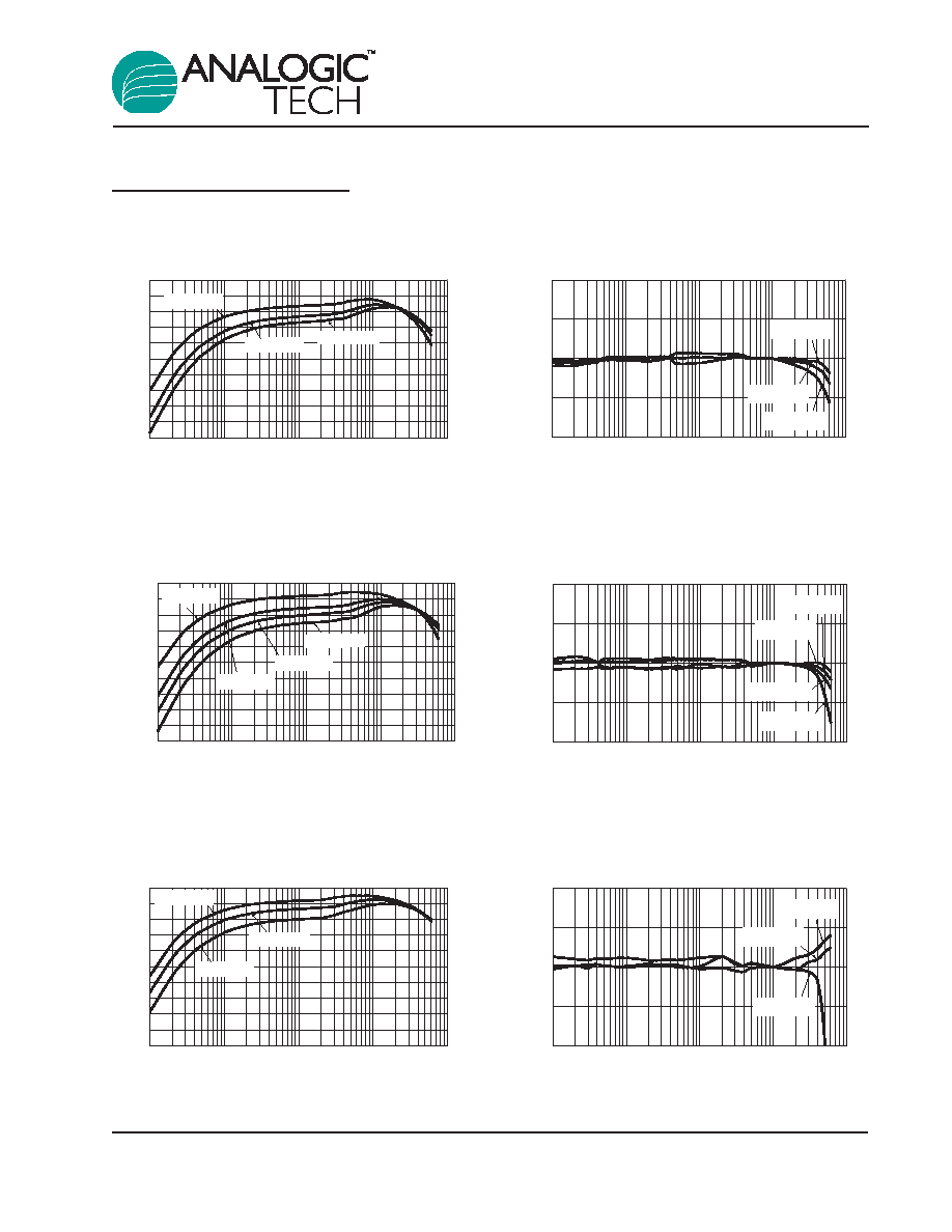
Typical Characteristics
EN1 = V
IN
; EN2 = GND.
DC Regulation
(V
OUT
= 3.3V; L = 6.8µH)
Output Current (mA)
Output Error (%)
-1.0
-0.5
0.0
0.5
1.0
0.1
1
10
100
1000
V
IN
= 5.0V
V
IN
= 4.2V
V
IN
= 3.6V
Efficiency vs. Load
(V
OUT
= 3.3V; L = 6.8
H)
Output Current (mA)
Efficiency (%)
50
60
70
80
90
100
0.1
1
10
100
1000
V
IN
= 3.6V
V
IN
= 4.2V
V
IN
= 5.0V
DC Regulation
(V
OUT
= 2.5V)
Output Current (mA)
Output Error (%)
-1.0
-0.5
0.0
0.5
1.0
0.1
1
10
100
1000
V
IN
= 5.0V
V
IN
= 3.6V
V
IN
= 3.0V
V
IN
= 4.2V
Efficiency vs. Load
(V
OUT
= 2.5V; L = 6.8
H)
Output Current (mA)
Efficiency (%)
50
60
70
80
90
100
0.1
1
10
100
1000
V
IN
= 5.0V
V
IN
= 3.6V
V
IN
= 4.2V
V
IN
= 2.7V
DC Regulation
(V
OUT
= 1.8V)
Output Current (mA)
Output Error (%)
-1.0
-0.5
0.0
0.5
1.0
0.1
1
10
100
1000
V
IN
= 4.2V
V
IN
= 3.6V
V
IN
= 2.7V
Efficiency vs. Load
(V
OUT
= 1.8V; L = 4.7
H)
Output Current (mA)
Efficiency (%)
50
60
70
80
90
100
0.1
1
10
100
1000
V
IN
= 2.7V
V
IN
= 3.6V
V
IN
= 4.2V
AAT2512
Dual 400mA High Frequency Buck Converter
2512.2006.06.1.4
5